
Quick answer: ecology unit installation is decided by four site facts, and the airflow rating is not one of them. A three-stage train is three separate modules in series, so what governs is the straight duct run available, the load the hangers or the slab will carry, the static pressure the fan selection left for treatment, and the clear space on the access side of each module. The last of those is the one that most often breaks a layout: our UV and carbon modules publish a maintenance clearance of D = 1,000 mm, and a unit that fits the duct but cannot be opened is a problem you install once and pay for every service visit afterwards.
This guide helps you decide whether a three-stage train will physically go into the position you have, and what to record before anyone quotes. It does not select a model, size the airflow, or price installation labor. For configuration and quotation, see the kitchen ecology unit page; for what the equipment actually is, start with what is an ecology unit.
| Site situation | Critical input | Initial route | Still needs confirmation |
|---|---|---|---|
| Long straight run available in a plant room | Available in-line length | Three modules in line, in stage order | Access side clearance at each module |
| Short run, generous height | Ceiling void or riser height | Stacked arrangement | Support loading and the transition pieces |
| Nothing fits in one place | Where each stage could sit | Split the train along the route | Stage order must survive the split |
| Existing fan, no spare pressure | Static pressure allowance for treatment | Stage count reviewed before layout | Resistance of each stage at your airflow |
| Retrofit replacing existing equipment | Interface of the existing opening | Survey the opening first | Covered separately in the replacement guide |
What a three-stage train actually occupies
Catalog pages give airflow ranges. What a mechanical contractor needs at layout stage is length, and length is the sum of three module envelopes plus whatever the connections between them take. Because our modules are published per model, that sum can be worked out on paper before anything is ordered.
Take a duty of 8,000 m³/h, which is a common size for a single busy kitchen, and put the three stages that make up a full ecology unit against it.
| Stage | Model at 8,000 m³/h | Module envelope L × W × H (mm) | Flange (mm) | Weight (kg) |
|---|---|---|---|---|
| 1. Electrostatic precipitation | LK80E1 | 1,524 × 560 × 833 | 1,277 × 614 | 116 |
| 2. UV-C photolysis | UV80 | 1,511 × 431 × 833 | 1,316 × 653 | 55 |
| 3. Activated carbon | CB80 | 1,427 × 800 × 833 | 1,316 × 653 | 215 |
| Train total | — | 4,462 mm of module length | — | 386 kg |
Read the total carefully. The 4,462 mm figure is the sum of the three published module envelopes and nothing else. It does not include the connections between modules, any transition required where a flange does not match the duct, or the room a fitter needs to make up a joint. Treat it as the floor of the space requirement, not the requirement itself, and confirm the final dimension against the configuration drawing for your actual models.
Decision rule. IF the available straight run is below the module total plus connections, THEN the route is a stacked arrangement or a split location rather than a smaller unit, BECAUSE reducing the module size means reducing the airflow the train can treat, and the airflow is set by the kitchen rather than by the plant room. Where the duct section itself is what is tight, the interaction between section, velocity and pressure is worked through in commercial kitchen exhaust duct size.
Weight, and what carries it
Three hundred and eighty-six kilograms distributed along four and a half meters of duct is not a heavy load by structural standards, but it is not a duct load either, and it rarely appears on the original hanger schedule when treatment is added to a project late.
Two features of that number are worth noticing. The carbon stage is the heaviest single item, at 215 kg in this example, because it holds media rather than plates or lamps. And the weight is not distributed evenly along the run, so the support arrangement is designed against three point loads rather than an average.
The practical consequence is a question, not a calculation: whoever owns the ceiling or the plant room floor needs the module weights before the layout is fixed, not after the equipment arrives. Ask for the weights by model at the same time as the dimensions, and give them to the structural or mechanical engineer as three separate items. In a Gulf mall or tower, the landlord’s fit-out manual can ask for the unit type, the shop drawings and the airflow calculations at design approval; which text asks for which document is on our ecology unit requirements page.
The clearance that decides the layout
This is the section that saves the most money, and it is the one most often skipped.
Every stage in an ecology unit has to be opened on a routine basis. The precipitator cells are withdrawn for washing. The UV lamps are replaced on a schedule. The carbon panels are exchanged when the media is spent. All three operations happen from the access side of the module, which means what matters is the clear distance from that face to the nearest obstruction — not to the wall, and not on the drawing, but in the space as it will actually be built with services routed through it.
Our UV and carbon modules publish a maintenance clearance of D = 1,000 mm on the access side. The precipitator stage needs the clear length to withdraw its cell, which is model-specific and confirmed with the configuration proposal.
What it costs the fan, and which figures are published
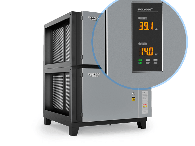
Each stage adds resistance, and the sum has to sit inside whatever the fan selection left for treatment. That allowance is usually set by whoever selected the fan and is rarely revisited when stages are added later, which is why it is worth extracting as a number before the stage list is agreed.
We would rather be exact about what we publish here than give a confident-looking total that is not traceable, so the position is set out stage by stage.
| Stage | What we publish | What it does not tell you | What to ask for in writing |
|---|---|---|---|
| Electrostatic precipitation | Complete module rated at no more than 150 Pa with its airflow distribution plate; the cell itself contributes roughly 20 to 30 Pa. Brochure equipment resistance is 31 Pa on E0, 23 Pa on E1 and 34 Pa on E2 | The figure at a loaded condition rather than a clean one | Pressure drop at your design airflow, stated clean and loaded |
| UV-C photolysis | No published series figure. One measured value exists for a single model: 65 Pa on a UV80, from test report 2018I20-35-1594159016. Stage resistance is otherwise issued per model with the configuration proposal | Anything about the other seven models in the range | The resistance for the specific model being offered, at your airflow |
| Activated carbon | Brochure equipment resistance of 150 Pa across CB30 to CB150; verify total system static pressure with your fan | How the figure moves as the media loads | The figure at your airflow, and how it is expected to change in service |
This table answers what is and is not on record. It does not give you a system total, and deliberately so: adding three numbers taken from different bases — one complete-module rating, one single-model measurement and one brochure figure — would produce a tidy number that no test supports. The same trap in a commercial setting, where two quotations state resistance on different bases and in different units, is worked through in ecology unit price. The useful move is the opposite one. Take your design airflow to the supplier, ask for each stage at that airflow in writing, and compare the sum against the allowance you were given.
Field note on the order of work. The pressure allowance question is worth asking before the stage list is agreed, not after. Once the stages are chosen and the drawing is issued, a shortfall in the allowance turns into either a fan change or a stage deletion, and the stage that gets deleted is usually the one added last, which in a three-stage train is the carbon — the stage that was there to answer the smell complaint in the first place.
Power, stage order, and what is not included
Supply at the position
Our units are configured to order for 220 V or 380 V at 50 or 60 Hz, so the supply is matched to the site rather than the other way round, but it has to be stated at order rather than assumed. Record what is actually at the isolator, with voltage, phase and frequency, and note that each module is an electrical item in its own right: the precipitator stage has its high-voltage power supply, and the UV stage has its lamps and ballasts.
Stage order, which is not negotiable
Grease filters in the hood, then electrostatic precipitation, then UV-C, then activated carbon. The reason is physical rather than conventional: the gas-phase stages are damaged by what the particle stages are there to remove. Grease reaching a lamp array or a carbon bed ends that stage’s useful life long before its design life. If a layout constraint forces the train to be split along the route, the order still has to survive the split.
What is not in the equipment supply
The fan is not part of the standard scope, although it can be supplied with the train and matched to the total static pressure of the configuration if you want it quoted that way. Not supplied at all are the ductwork, the transition pieces between the duct and the module flanges, installation labor and commissioning attendance. Our whole-unit warranty runs twelve months and covers the collection cells and the high-voltage power module; UV lamps and activated carbon media are consumables and are not covered; labor and site attendance are quoted separately. Common spare parts are held in stock, and parts remain available for one year after a model is discontinued. Minimum order is one unit and standard lead time is 7 to 15 days. Buying directly from the factory for a UAE project? The same split applies, and the full terms and submission documents are on our ecology unit supplier page for UAE projects.
Scope and limits
Three layers clear separately, and passing one does not clear the next. Layer one, equipment data: dimensions, weights and published resistances describe the modules. Layer two, site installation: straight run, support, access and supply are facts about your building that no datasheet addresses. Layer three, whole-system operation: delivered airflow, capture at the hood and service discipline decide the result at the discharge. Passing one layer does not clear the next.
Specific limits on this page:
- The worked example is dimensional arithmetic, not a configuration. It adds three published module envelopes at one duty. Your models, connections and transitions will produce a different figure, and the number to build to is the one on the configuration drawing.
- We do not publish a BIM or Revit family for this equipment. If your workflow needs one, say so and we will supply the dimensional data by model so your team can build the object; we would rather tell you that than leave you searching for a file that does not exist.
- No carbon change interval and no lamp replacement schedule is given here. Both are set in writing for the specific site with the configuration proposal, because both follow the cooking process, the hours and the load.
- No ozone figure is given for the UV-C stage, because we do not publish one. If ozone is a condition on your project, raise it as a project question before the stage is specified.
- Installation work itself is not described here. This page is about whether the equipment fits and what to record; the physical installation, electrical connection and commissioning belong to a competent contractor working to the installation documentation issued with the equipment.
- Nothing here is a compliance determination. What your local authority requires at the discharge is a question for your engineer and that authority.
Pre-installation checklist
Fill this in before asking anyone to propose an ecology unit, and the same sheet works for every supplier you approach.
Duty. Design airflow in m³/h, and which stages are actually required — precipitation only, precipitation plus UV-C, or all three. Which stages are justified for your cooking process is covered in what is an ecology unit.
Straight run. The in-line length available at the intended position, measured in the space. If it is short of the module total plus connections, note the ceiling void height so a stacked arrangement can be assessed instead.
Access. The clear distance in front of the access face of each module, measured to the nearest obstruction rather than to the wall, against the published D = 1,000 mm for the UV and carbon modules.
Load. What the hangers or the slab will carry at that position, against the sum of the module weights as three separate point loads.
Pressure. The static pressure allowance the fan selection left for treatment, and who owns that number.
Power. Voltage, phase and frequency at the isolator.
Ask every supplier, in writing: module dimensions, flange sizes and weights by model; the resistance of each stage at your airflow; the clear access dimension each module needs; what is excluded from the equipment supply; the warranty boundary including which items are consumables; and what they will not commit to without a site review.
What is still missing at that point is measured airflow, which arrives from commissioning rather than from any supplier. What would send you back to the start: a change in the cookline that moves the extract rate, a duct route alteration, a fan change, or a stage added after the layout was fixed.
Key takeaways
- Four facts decide it: straight run, support load, pressure allowance and access clearance — the airflow rating only produces a shortlist.
- Length: three published module envelopes at 8,000 m³/h total 4,462 mm before any connection is added; treat that as a floor.
- Weight: three point loads rather than an average, and the carbon stage is the heavy one.
- Access: D = 1,000 mm on the published modules, measured in the space and not on the drawing.
- Pressure: ask for each stage at your airflow in writing rather than adding published figures taken from different bases.
Frequently Asked Questions
- How much space does an ecology unit need?
- More than the duct dimensions suggest, because it is three modules in series rather than one box. As a worked example at a duty of 8,000 cubic meters per hour, our published module envelopes are 1,524 mm for the electrostatic stage, 1,511 mm for the UV-C stage and 1,427 mm for the activated carbon stage, which is 4,462 mm of module length before any connection between them is counted. Add the connections and any transition required where a flange does not match the duct, and allow the clear access space in front of each module separately. Where the straight run is short, the alternative is a stacked arrangement or splitting the stages along the route rather than choosing smaller modules, because module size follows the airflow the kitchen needs.
- How much clearance does an ecology unit need for maintenance?
- Our UV and activated carbon modules publish a maintenance clearance of D = 1,000 mm on the access side, and the electrostatic stage needs the clear length to withdraw its collection cell, which is model-specific and confirmed with the configuration proposal. The important part is where the measurement is taken. Measure from the access face to the nearest obstruction as the space will actually be built, including pipework, cable trays and lighting, rather than to the wall on a drawing. Every stage has to be opened routinely over the life of the installation: cells are withdrawn for washing, lamps are replaced on a schedule and carbon panels are exchanged when the media is spent. A module that fits but cannot be opened converts a one-time layout decision into a permanent maintenance cost.
- How much pressure drop does an ecology unit add?
- Ask for it stage by stage at your design airflow rather than accepting a system total, and here is our own position so you can see why. The electrostatic stage is rated as a complete module at no more than 150 Pa with its airflow distribution plate, with the cell itself contributing roughly 20 to 30 Pa, and brochure equipment resistance is 31 Pa on E0, 23 Pa on E1 and 34 Pa on E2. For the UV-C stage we do not publish a series figure; one measured value exists for a single model, 65 Pa on a UV80 from test report 2018I20-35-1594159016, and resistance is otherwise issued per model with the configuration proposal. For activated carbon the brochure equipment resistance is 150 Pa across CB30 to CB150, and total system static pressure should be verified with your fan. Adding figures taken from three different bases would produce a total that no test supports.
- Can the stages of an ecology unit be installed in a different order?
- No, and the reason is physical rather than conventional. The order is grease filters in the hood, then electrostatic precipitation, then UV-C, then activated carbon, because the gas-phase stages are damaged by exactly what the particle stages exist to remove. Grease reaching a lamp array or a carbon bed disables that stage long before its design life, so an out-of-order train buys a running cost rather than a result. Where a layout constraint forces the stages to be split between two locations along the duct route, the sequence still has to survive the split. If a proposal you have been given places carbon or UV-C ahead of particle removal, that is worth querying before anything else in the offer.
- What is not included when you buy an ecology unit?
- The fan is not part of the standard scope, but it can be supplied with the train and matched to the total static pressure of your configuration if you ask for it that way. What is not supplied at all is the ductwork, the transition pieces between the duct and the module flanges, installation labor and commissioning attendance. On the warranty side, ours runs twelve months on the whole unit and covers the collection cells and the high-voltage power module, while UV lamps and activated carbon media are treated as consumables and are not covered, and labor and site attendance are quoted separately. Common spare parts are held in stock and parts remain available for one year after a model is discontinued. Minimum order is one unit and standard lead time is 7 to 15 days. Establish the exclusions in writing with any supplier before comparing two prices, because an offer that includes transitions and one that does not are not the same offer.
Checking whether a three-stage train fits your plant room?
Send us six figures you can take with a tape and one phone call: design airflow, the in-line length available, the clear access distance at the intended position, the load the support will carry, the static pressure allowance left for treatment, and the supply at the isolator. We will tell you whether the train fits in line or needs stacking, what each stage would add in resistance at your airflow, where the access clearance falls short, and what we would not commit to without a site review. You get back a layout answer with dimensions, not a brochure.
Send us your plant room dimensions
Law manages project delivery at Polygee, from application review and equipment configuration through interfaces, installation support and handover documentation for consultants, contractors and dealers. Polygee, founded in 2004, manufactures commercial kitchen exhaust filtration equipment. This article is a planning aid based on published module data; it is not a mechanical design, not an installation instruction, and not a substitute for a site survey.
References & sources
- Polygee — module dimensions, flange sizes, weights and maintenance clearances by model, from the product specification tables; test report 2018I20-35-1594159016 for the measured UV80 resistance. polygeeesp.com
- Building Engineering Services Association — DW/172, Specification for Kitchen Ventilation Systems, the reference specification for kitchen extract systems and in-line equipment access in the United Kingdom. thebesa.com
- International Code Council — 2021 International Mechanical Code, Section 506.3.4, air velocity in grease duct systems, which constrains the duct the train is installed into. codes.iccsafe.org
- UL Standards & Engagement — UL 867, Standard for Electrostatic Air Cleaners, the product safety standard applied to the electrostatic stage. shopulstandards.com
Related reading
- What is an ecology unit — the three stages, what each one controls, and which stages a given cooking process actually justifies.
- Commercial kitchen ESP replacement — the parallel exercise when equipment is already installed and the interface is fixed.
- Commercial kitchen exhaust duct size — how duct section, velocity and pressure interact around an in-duct treatment stage.
- Electrostatic precipitator cleaning and maintenance — what the access clearance is actually for, visit by visit.