

Commercial kitchen exhaust duct size is the one dimension on a ventilation drawing that most people get backwards, because the instinct carried over from a domestic kitchen is exactly wrong here. In a house, a bigger duct is generally a better duct: less noise, less resistance, an easier fan. In a Type I system the code does not give you a diameter at all. It gives you a floor on how fast the air has to move — the 2021 International Mechanical Code, Section 506.3.4, asks for an air velocity within the duct system of not less than 500 feet per minute — and that floor, combined with your design airflow, sets a maximum cross-section. Go above it and the duct stops being a passage and starts being a place where grease settles. This guide works the arithmetic in the open, sets out the clauses that follow once the size is fixed, and then does the part almost no page does: explains what the duct section decides about the in-duct equipment that has to live inside it.
This guide helps you decide what cross-section your grease duct needs and what that size then commits you to downstream. It does not calculate your hood exhaust rate, design the duct run, or select a fan. For the airflow that feeds this calculation, see commercial kitchen hood CFM requirements; for how the duct itself must be built, grease duct requirements.
| Application | Critical input | Initial route | Still needs confirmation |
|---|---|---|---|
| New Type I hood system | Design exhaust rate in CFM | Divide by 500 fpm for the maximum area the velocity floor allows, then size below it | The code edition your authority enforces, and any local amendment |
| Existing duct, adding treatment | Actual duct dimensions and measured airflow | Calculate the velocity you really have before selecting an electrostatic precipitator | Static pressure still available, and service access at the cell |
| Duct that keeps needing cleaning | Velocity, slope and cleanout spacing | Check whether the section is oversized before blaming the filters | Whether the hood is capturing at source in the first place |
| Residential or Type II run | Hood classification | This page does not apply — different rule set entirely | Which hood type the appliance line actually requires |
| Hood collar does not match the duct | Transition length | Transitions are allowed, but the velocity exception covers only up to 3 feet | Whether the transition is built to shed grease rather than trap it |
Why a commercial duct is not a bigger range hood duct
Search for kitchen exhaust duct size and the results arrive mixed together: forum threads about a house extension, articles comparing 6-inch against 8-inch against 10-inch round duct, and, scattered among them, code pages written for restaurants. The advice in the two groups points in opposite directions, and the reason is worth stating plainly before any arithmetic.
A residential range hood duct is sized mainly against resistance. The fan has a fixed capability, the run is short, and a larger duct lowers pressure drop and noise. Nothing much is being carried except air and steam, so there is no penalty for going up a size.
A Type I grease duct is a conveyor. What leaves a commercial cookline is an aerosol of oil droplets and smoke, and it stays airborne only while the airstream is moving fast enough to keep it there. Slow the air down and the heavier fraction leaves the airstream and lands on the duct wall, where it accumulates between cleans. That is why the code sets a floor on speed instead of a limit on size, and it is why an oversized commercial duct is a defect rather than a margin.
Decision rule. If the hood is a Type I hood over grease-producing appliances, size the duct downward from the velocity floor and treat any instinct to “go one size up for safety” as the residential habit it is. Key point: in a Type I system, spare cross-section is not spare capacity; it is settled grease.
The number that sets the size, and the arithmetic
The clause is short. The 2021 International Mechanical Code, Section 506.3.4, headed Air velocity, reads:
Two consequences follow immediately, and they are the whole of the sizing method.
First, airflow divided by velocity gives area. If the hood schedule says 4,000 CFM and the floor is 500 feet per minute, then 4,000 divided by 500 is 8 square feet, and 8 square feet is the largest cross-section that still meets the clause. Multiply by 144 to work in square inches if the duct is rectangular: 8 square feet is 1,152 square inches, which a 36 by 32 inch duct would just exceed and a 36 by 30 inch duct would sit inside.
Second, the floor is a floor, not a design target. Sizing to land exactly on 500 fpm leaves nothing for the conditions the duct actually meets: a filter bank that has loaded since the last service, an electrostatic precipitator whose cells have collected since the last clean, a damper or fitting that was not in the original calculation, a fan that delivers less than its curve once the system is real. Designers therefore sit above the floor, and the margin they choose is an engineering judgement rather than a code number.
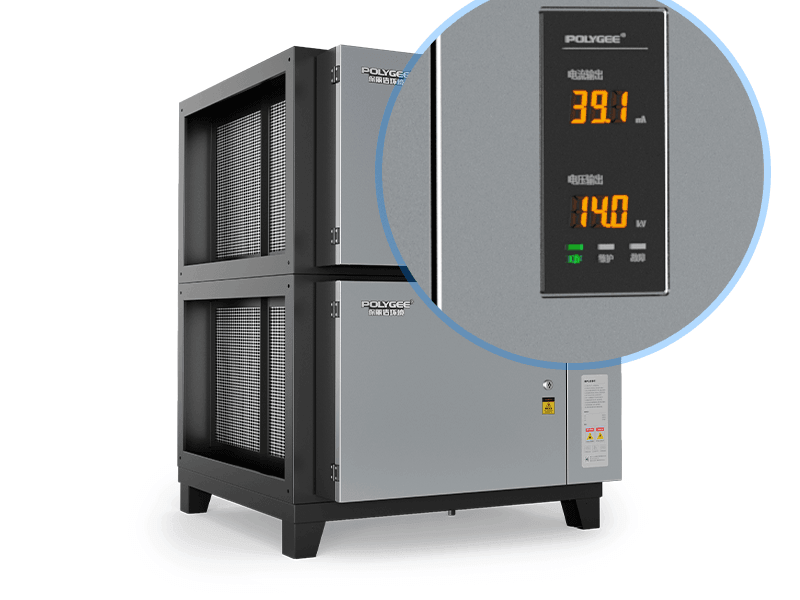
There is a third consequence that only shows up on projects with treatment in the run, and it is the reason the sizing conversation and the equipment conversation cannot be held separately. The velocity floor applies within the duct system, and an in-duct electrostatic precipitator is part of that system. Its housing is generally wider than the duct it replaces a section of, because the collection cells need face area to work across. So the unit is a deliberate local drop in velocity, bounded by transitions at each end — which is precisely the arrangement the 3-foot transition exception was written for. Size the duct without knowing whether a precipitator is coming, and you can end up with a section that leaves no room to make those transitions short enough.
| Design exhaust rate | Maximum area at the 500 fpm floor | In square inches | A rectangular duct at or below it | Resulting velocity |
|---|---|---|---|---|
| 1,500 CFM | 3.0 sq ft | 432 sq in | 24 × 16 in = 384 sq in | 563 fpm |
| 2,500 CFM | 5.0 sq ft | 720 sq in | 30 × 20 in = 600 sq in | 600 fpm |
| 4,000 CFM | 8.0 sq ft | 1,152 sq in | 36 × 24 in = 864 sq in | 667 fpm |
| 6,000 CFM | 12.0 sq ft | 1,728 sq in | 42 × 30 in = 1,260 sq in | 686 fpm |
| 8,000 CFM | 16.0 sq ft | 2,304 sq in | 48 × 36 in = 1,728 sq in | 667 fpm |
A smaller duct is usually the better candidate when the run is short and the fan has static pressure to spare. A larger duct remains better when the run is long or convoluted, provided the velocity still clears the floor with margin. This table answers what the velocity clause permits. It does not answer what your system needs: the duct sizes in the fourth column are worked examples of the arithmetic, not recommendations, and the pressure drop that each one produces over your particular run is a calculation for your mechanical engineer.
What the code fixes once the size is settled
Size is the first decision, and several others follow from it rather than being independent. These are the clauses that most often turn into a site problem when the duct route was drawn before they were read.
| Clause | What it fixes | What it supports | What it does not prove | Buyer check |
|---|---|---|---|---|
| IMC 2021 §506.3.4 | Air velocity not less than 500 fpm in a Type I grease duct; transitions exempt up to 3 ft if designed to prevent grease trapping | A maximum cross-section for a given airflow | That the velocity is achieved once the system is dirty, or that the fan will deliver the design airflow | Ask for the calculated velocity at design airflow, in writing |
| IMC 2021 §506.3.1.1 | Steel not less than 0.0575 in (No. 16 gage), or stainless not less than 0.0450 in (No. 18 gage); exception for factory-built grease duct listed and labeled to UL 1978 | The material and thickness of the duct wall | Anything about the joints, which are a separate clause | Confirm gage and material on the submittal, not the quotation |
| IMC 2021 §506.3.2 | Joints, seams and penetrations made with a continuous liquid-tight weld or braze on the external surface | That a compliant grease duct is welded, not sealed or taped | Weld quality, which is an inspection matter | Agree who witnesses the joints before the enclosure closes |
| IMC 2021 §506.3.7 | Slope of not less than one-fourth unit vertical in 12 units horizontal, a 2-percent slope, toward the hood or a grease reservoir | That horizontal runs drain rather than pool | That the slope survives the ceiling void it has to cross | Check slope against available headroom at the coordination stage |
| IMC 2021 §506.3.9 | Horizontal cleanouts not more than 20 ft apart, and not more than 10 ft from direction changes greater than 45 degrees | That the run can be cleaned along its length | That the cleanouts are reachable once ceilings and services are in | Mark cleanout positions on the reflected ceiling plan |
| IMC 2021 §506.3.6 | Clearance of not less than 18 in to combustible construction, 3 in to noncombustible and to gypsum wallboard on noncombustible structures, where enclosures are not required | The space the duct needs around it | The enclosure requirements where clearance cannot be kept | Resolve clearance before the duct route is fixed, not after |
The reason these belong in a sizing guide rather than in a separate construction note is that they compete for the same space. A duct sized correctly for velocity, sloped at 2 percent, held 18 inches off combustible construction and provided with a cleanout every 20 feet is a set of demands on a ceiling void that were all decided the moment the cross-section was chosen. Where they cannot all be met, the resolution is a design conversation, and it is cheaper before the route is drawn than after.
What the duct section decides about in-duct equipment
This is the part that is missing from almost every page on this subject, and it is the part that costs money when it is discovered late. If the project includes any in-duct treatment — and for a kitchen discharging near neighbours or into a shared courtyard it usually does — the duct dimensions have already made most of the decisions before a supplier is contacted.
An in-duct electrostatic precipitator is selected against two things at once: the airflow it has to treat, and the section it has to sit in. The airflow comes from the hood schedule. The section comes from the calculation above. Where the two do not line up with a standard unit, the answer is a transition, and transitions are exactly what Section 506.3.4 limits to 3 feet before its velocity exception stops applying.
| What the duct size decides | Why it matters | Record this before requesting a quotation | What goes wrong when it is skipped |
|---|---|---|---|
| Whether a transition is needed, and how long | The velocity exception covers transitions only up to 3 ft | Duct dimensions at the proposed unit position | A long taper that satisfies nobody: not the fitter, not the inspector |
| Static pressure left for treatment | The fan was selected against a total; a treatment stage adds to it | Static pressure allowance in in. w.g., and who set it | Design airflow is never achieved, and the velocity floor is missed as a consequence |
| Straight run available | Units need approach and departure lengths to see even flow | Distance to the nearest fitting either side | Uneven flow across the cell, and performance that cannot be reproduced |
| Service access at the cell face | Collection cells are withdrawn sideways for cleaning | Clear dimension on the access side, in inches | A unit that fits the duct and cannot be opened in the plant room |
| Weight and support | Duct bracing was designed for duct, not for equipment | Whether the run has independent support at the unit | Load transferred into a duct hanger that was never sized for it |
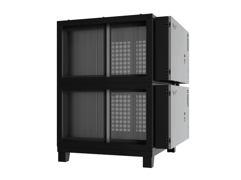
Decision rule. IF the project will include in-duct treatment THEN fix the duct section, the static pressure allowance and the access clearance in the same conversation, BECAUSE all three are consequences of the size and all three are expensive to change once the duct is fabricated. Field note: the number most often missing from an enquiry is not the airflow. It is the clear dimension on the service side.
It is worth being concrete about what changes with the section, because “it depends” is not useful when a drawing is due. A given design airflow can be carried by a tall narrow duct or a short wide one, and the velocity is identical either way — but an electrostatic precipitator is not indifferent between them. The cells sit across the airstream, so the face the unit presents has a shape as well as an area, and a housing that matches a 36 by 24 inch duct is not the same product as one matching 24 by 36. Where the run is already drawn, send the orientation with the dimensions. Where it is not yet drawn, ask what shape suits the treatment stage before the route is fixed, because at that point it costs nothing to accommodate and later it costs a transition.
The same logic runs the other way for projects that are retrofitting rather than building. If a duct is already in place and the brief is to add filtration, the section is a given and it has already ruled out some configurations. The first measurement to take is not the airflow — it is the duct dimensions and the free length, because those decide whether an in-duct precipitator is the right form at all, or whether a packaged unit outside the duct run is the more realistic route.
Where the treatment train is delivered as a packaged assembly rather than as a section of the duct run, the same constraints apply but move inside a single enclosure; that is the arrangement usually called an ecology unit, and its footprint has to be coordinated against the plant space rather than against the duct alone.
Scope and limits
The arithmetic on this page is arithmetic. It tells you what a velocity floor implies for a cross-section, and nothing else. Passing one layer does not clear the next.
- A calculated velocity is not a measured velocity. The figure that matters at handover comes from a commissioning traverse, not from a spreadsheet. Next step: agree who measures it, and at what point in the run, before the system is signed off.
- The code edition matters and varies. Section numbers and figures move between editions, and local amendments can be stricter. Next step: confirm the adopted document and edition for your address before designing to any number here.
- Sizing is not a fan selection. Cross-section sets velocity; the fan has to overcome the resistance that section produces along the whole run, including any treatment stage. Next step: give the fan supplier the complete resistance schedule, not the duct size alone.
- This page does not size equipment. Airflow and section narrow the choice; they do not make it. Next step: send the duct dimensions, airflow and access clearance and ask for a configuration against them.
- A duct sized correctly is not a treated exhaust. Velocity keeps grease moving along the duct; it does not remove it from the airstream. That is what an electrostatic precipitator in the run is for, and it is a separate decision with its own evidence. Next step: if the discharge is near neighbours or into a courtyard, treat sizing and treatment as one design conversation rather than two purchases.
- An oversized duct is not fixed by adding equipment. Putting an electrostatic precipitator into a run whose velocity has already dropped below the floor leaves grease settling upstream of the unit, where nothing collects it. Next step: correct the section first, then select the treatment stage against the corrected figures.
- Nothing here is a compliance determination. We are an equipment manufacturer, not your engineer and not the authority having jurisdiction. Next step: put the sized drawing in front of both.
Buyer record
Before you request a quotation, record: the design exhaust rate in CFM and where it came from; the proposed duct dimensions and the velocity they produce; the length of any transition at the unit position; the straight run available either side; the static pressure allowance left for treatment and who set it; and the clear access dimension on the service side.
Ask every supplier for: pressure drop at your design airflow, stated both clean and loaded; the connection dimensions and whether a transition is required; the clearance needed to withdraw the cell; the support arrangement the unit expects; and a plain statement of what they will not commit to without a site review.
If an electrostatic precipitator is in the scope, add three lines to that record: the orientation of the duct at the unit position, not just its area; the length available for a transition at each end against the 3-foot figure in the exception; and who owns the static pressure allowance, because that number is usually set by whoever selected the fan and is rarely revisited when treatment is added later.
What is still missing at that point is the measured airflow, which arrives from commissioning rather than from any supplier. What triggers a resize: a change in the appliance line that moves the hood exhaust rate, a change of duct route that adds length or bends, the addition of a treatment stage that was not in the original resistance schedule, or adoption of a different code edition mid-project.
Key takeaways
- Direction: size the duct down from a velocity floor, not up from a collar, because the code constrains speed rather than diameter.
- Arithmetic: airflow divided by 500 fpm gives the maximum area the clause allows — a ceiling to stay under, not a target to hit.
- Oversizing: treat spare cross-section as settled grease, not as safety margin.
- Transitions: allowed, but the velocity exception stops at 3 feet, so a long taper is not a solution to a mismatched collar.
- Downstream: record static pressure allowance and service access at the same time as the section, because both are consequences of it and neither is cheap to change later.
Frequently Asked Questions
- What size duct do I need for a commercial kitchen exhaust?
- Work it from the airflow and a velocity floor rather than from a diameter. The 2021 International Mechanical Code, Section 506.3.4, requires grease duct systems serving a Type I hood to be designed and installed to provide an air velocity within the duct system of not less than 500 feet per minute. Turn that into a size by dividing the design exhaust rate by 500: a 4,000 CFM system gives 4,000 divided by 500, which is 8 square feet, and that is the largest cross-section the velocity floor allows, not a target to aim at. In practice designers sit well above the floor, because velocity also has to survive a dirty duct, a loaded filter bank and any treatment stage in the run. The figure to bring to a supplier is the actual duct dimensions and the resulting velocity, not the hood collar size.
- Why can a commercial grease duct be too big?
- Because the duct is a conveyor, not just a passage. Grease leaves the cookline as an aerosol, and it stays airborne only while the airstream is moving fast enough to carry it. Enlarge the cross-section at a fixed airflow and the velocity falls in direct proportion, so the heavier fraction settles on the duct wall instead of travelling to the treatment stage or the terminal. That is why the code sets a floor rather than a ceiling, and it is the single biggest difference from residential range hood ducting, where a larger duct is generally treated as a way to reduce noise and pressure drop. In a Type I system an oversized duct converts an airflow decision into a cleaning and fire-risk decision.
- Can I use flexible duct for a commercial kitchen exhaust?
- Not for the grease duct itself. The 2021 IMC Section 506.3.1.1 requires grease ducts serving Type I hoods to be constructed of steel having a minimum thickness of 0.0575 inch, which is No. 16 gage, or stainless steel not less than 0.0450 inch, which is No. 18 gage, with an exception for factory-built commercial kitchen grease ducts listed and labeled in accordance with UL 1978 and installed in accordance with Section 304.1. Section 506.3.2 then requires joints, seams and penetrations to be made with a continuous liquid-tight weld or braze on the external surface. Flexible duct satisfies neither the material nor the joint requirement, so the question is really whether the run in question is a grease duct at all, and for a Type I hood it is.
- Does the duct size affect whether I can fit an in-duct air cleaner?
- It decides most of it. An in-duct electrostatic precipitator is selected against the airflow it has to treat and the cross-section it has to match, so the duct dimensions set the frame before any model is discussed. Three things follow from the size and are worth recording before you ask for a quotation: whether a transition is needed to reach the unit, and how long it is, because the velocity exception in Section 506.3.4 covers transitions only up to 3 feet; how much static pressure is still available for a treatment stage after the duct, filters and fittings have taken their share; and how much clearance exists on the service side to withdraw the collection cell. A unit that fits the duct but cannot be opened in the plant room is a maintenance problem you buy once and pay for repeatedly.
- Is the 500 fpm figure the same as NFPA 96 or my local code?
- Check the edition your authority actually enforces before designing to any number on a web page, including this one. The figure quoted here is from the 2021 International Mechanical Code, Section 506.3.4, which is the code adopted across much of the United States but not everywhere, and not in every edition simultaneously. Other documents in the same field, including NFPA 96, are adopted alongside or instead of it depending on the jurisdiction, and a local amendment can be stricter than the model code it amends. The safe order of work is to establish which document and which edition applies to your address, confirm the velocity requirement in that text, and only then size the duct. Nothing on this page is a compliance determination for a specific project.
Checking a duct section before the drawing is issued
Send us four numbers you already have: the design exhaust rate, the proposed duct dimensions, the straight run available where treatment would sit, and the clear dimension on the service side. We will work the velocity, tell you whether the section sits inside what the clause allows, and say what an in-duct stage would need from that run in terms of pressure allowance and access. You get back the worked calculation and a list of the questions that belong to your mechanical engineer rather than to us.
Law manages project delivery at Polygee, from application review and equipment configuration through interfaces, installation support and handover documentation for consultants, contractors and dealers. Polygee, founded in 2004, builds commercial kitchen exhaust filtration equipment. This article summarises published code text for planning purposes only — it is not a compliance determination for any project, and it is not a mechanical design. Confirm the adopted code and edition with your engineer and the authority having jurisdiction.
References & sources
- International Code Council — 2021 International Mechanical Code, Section 506.3.4 Air velocity; Section 506.3.1.1 Grease duct materials; Section 506.3.2 Joints, seams and penetrations of grease ducts; Section 506.3.6 Grease duct clearances; Section 506.3.7 Prevention of grease accumulation in grease ducts; Section 506.3.9 Grease duct horizontal cleanouts. codes.iccsafe.org
- UL Standards & Engagement — UL 1978, Grease Ducts, referenced by the IMC as the listing route for factory-built commercial kitchen grease duct. shopulstandards.com
- NFPA — NFPA 96, Standard for Ventilation Control and Fire Protection of Commercial Cooking Operations, adopted alongside or instead of the IMC depending on jurisdiction. nfpa.org
- Polygee — in-duct commercial kitchen exhaust filtration range, connection dimensions and pressure-drop data on request. polygeeesp.com
Related reading
- Commercial kitchen hood CFM requirements — where the airflow that feeds this calculation comes from, and what sets it.
- Grease duct requirements — how the duct itself is built once the section is decided: materials, welds, enclosure and clearance.
- Commercial kitchen exhaust termination requirements — where the run ends, and the distances that govern it.
- Commercial kitchen exhaust fan requirements — the fan that has to overcome everything the section and its fittings add up to.