

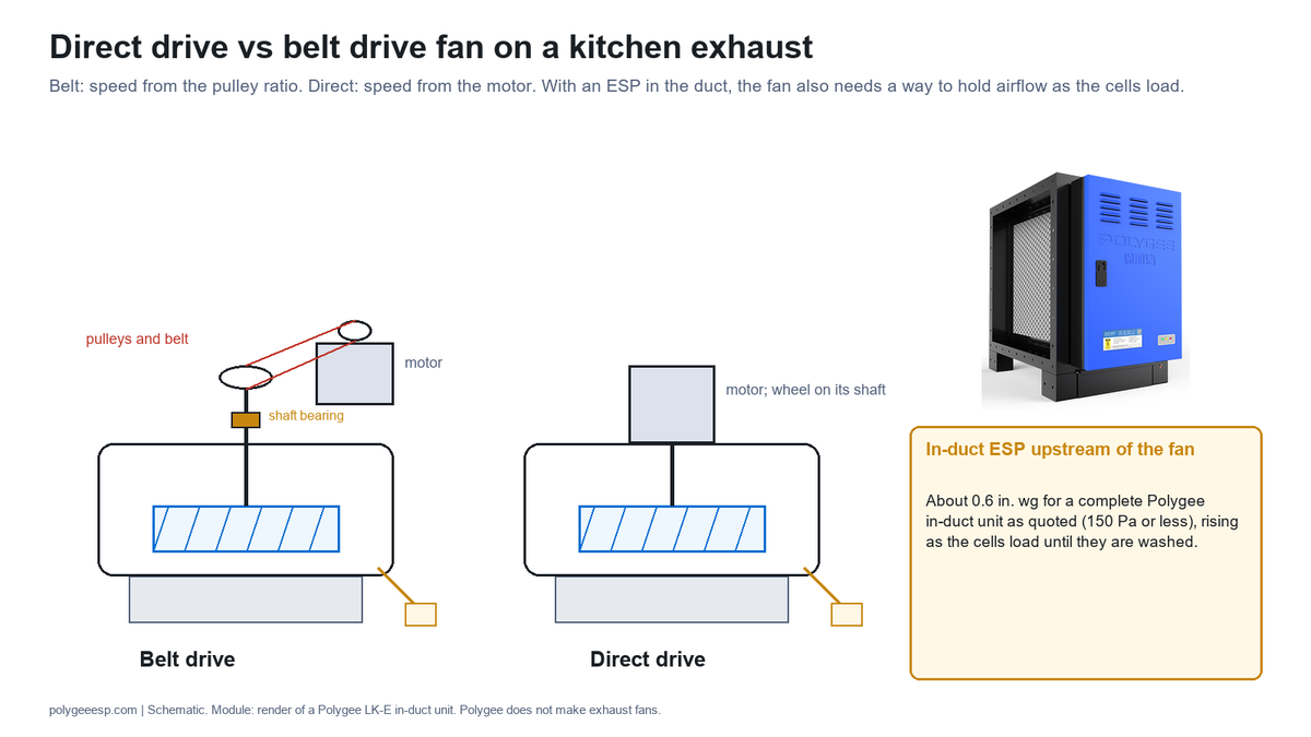
A belt drive fan turns its wheel through two pulleys and a belt, so its speed is set by the pulley ratio; a direct drive fan carries the wheel on the motor shaft, so its speed is the motor’s speed. On a kitchen exhaust, the direct drive vs belt drive fan choice decides how the fan is brought back to its design airflow when the resistance in the duct rises, and what has to be serviced on a fan that exhausts grease-laden air to keep it there.
That rise in resistance is where our equipment comes in. An in-duct electrostatic precipitator, or a kitchen ecology unit with UV-C and activated carbon stages behind it, adds a section to the grease duct whose resistance the fan has to overcome, and two of the documents read for this page state that airflow falls, or resistance rises, as the filters in the run load. Polygee does not make exhaust fans, and this page is written as a reader of the fan makers’ manuals, the codes and the government guidance on fan drives, with each figure attributed to the document it comes from.
This page helps you decide whether the exhaust fan on a grease duct, with or without a precipitator in it, should be belt driven or direct driven, and what to ask the fan maker and the treatment supplier before either is ordered. It ends with The 10-Line Kitchen Fan Drive Sheet, a record to attach to the fan enquiry or the retrofit brief. It gives no fan selection of ours and no procedure for changing belts, pulleys or drive settings: those follow the fan maker’s manual and are carried out by a qualified person.
| Question | Short answer |
|---|---|
| What is the difference? | Belt drive: wheel speed set by pulley diameters, adjustable by changing or opening the motor pulley. Direct drive: wheel on the motor shaft, speed set by the motor and any speed control fitted to it. |
| Which covers more duty? | In the one series compared here, the belt models have series maximums of 30,000 cfm and 5 in. wg and the direct models 14,700 cfm and 3 in. wg (Greenheck CUBE and CUE catalog); each maximum is a separate limit, not one operating point |
| Which needs less service? | Direct drive removes the belt, which the US Department of Energy fan sourcebook calls usually the most maintenance-intensive part of a belt-driven fan; bearings and motors are serviced on both |
| What does an ESP change? | It adds resistance that rises as its cells load, about 0.6 in. wg for a complete Polygee in-duct unit as quoted (150 Pa or less); the fan needs a way to hold the design airflow as that happens |
| How is airflow held? | Belt: a pulley reset with a motor current check, or a variable speed drive where one is fitted. Direct: the motor speed, through an EC motor or a variable frequency drive where the fan has one. A constant-flow controller with a variable speed drive does it automatically on either; each needs motor power in reserve |
| What is the code asking? | Not a drive type: listing or grease duct construction for the housing, motor outside the airstream, a hinged upblast fan, a grease drain, automatic fan control or an appliance interlock, and for a pollution control unit a pressure-drop alarm (IMC 2024) |
- Direct drive vs belt drive fan: what differs on a kitchen exhaust fan
- What the code asks of a kitchen exhaust fan, whichever the drive
- The published ranges: size, pressure, temperature and listing
- How a fan reaches its duty point: system curve and fan laws
- What an ESP adds: resistance that rises between washes
- Getting back to the design airflow on each drive
- Belts, bearings and motors on a grease exhaust fan
- Efficiency and noise: why the published figures disagree
- The 10-Line Kitchen Fan Drive Sheet
- Frequently asked questions
Direct drive vs belt drive fan: what differs on a kitchen exhaust fan
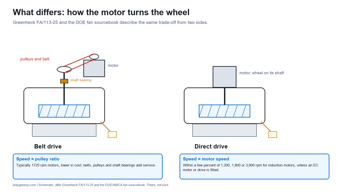
The two drives differ in one place: how the motor’s rotation reaches the wheel, and so how the wheel’s speed is set and changed. In a belt drive fan the motor turns a pulley, a belt carries the rotation to a second pulley on the fan shaft, and the shaft runs in its own bearings; the ratio of the two pulley diameters sets the wheel speed. In a direct drive fan the wheel is mounted on the motor shaft, there is no belt, no pulley and no separate shaft bearing, and the wheel turns at whatever speed the motor turns.
Greenheck’s motor application guide, FA/113-25, sets out what follows from that. The belt-driven fan has pulleys, shafts, bearings and belts, which add to the first cost and to periodic maintenance, but it generally uses lower-cost, higher-speed motors, typically 1725 rpm on 60 Hz; it is typically less efficient because of belt and bearing losses. The direct drive fan has specific motor speeds to make up for the lack of pulley adjustment, and motors below 1725 rpm, in the same guide’s words, cost more, are physically larger, have longer lead times and come in fewer options. The guide adds that direct drive motors suit places where access to bearings and belts is difficult, and that direct drive fans with variable frequency drives or electronically commutated (EC) motors give integral speed control for airflow balancing.
The Department of Energy’s fan sourcebook, written with the Air Movement and Control Association, puts the trade-off from the other side. Direct drives have higher efficiency, compact space requirements and lower maintenance, and the absence of a belt lets a fan run more reliably and more quietly; but a direct drive fan must rotate at the speed of the motor, typically 3,600, 1,800 or 1,200 rpm, and the sourcebook notes that most induction-motor direct drives run within a few percent of those synchronous speeds. A belt drive allows the speed to be adjusted by altering pulley diameters, which is why the same sourcebook says an error in estimating the duty can leave a direct drive system running inefficiently, and names an adjustable speed drive as one way to add speed flexibility.
| Point | Belt drive | Direct drive | Source |
|---|---|---|---|
| How wheel speed is set | Pulley diameter ratio; adjustable motor pulley for final balancing | Motor speed; EC motor or variable frequency drive where fitted | Greenheck FA/113-25; Greenheck Series C catalog p. 4 |
| Typical motor | 1725 rpm (60 Hz) and lower in cost | Specific speeds; below 1725 rpm costs more and takes longer to supply | Greenheck FA/113-25 p. 2 |
| Parts that wear | Belts, pulleys, shaft bearings, motor | Motor and its bearings | Greenheck FA/113-25 p. 1; DOE sourcebook p. 51 |
| Speed range without electronics | Set by the adjustable pulley range of the model | Within a few percent of 1,200, 1,800 or 3,600 rpm for induction motors | DOE sourcebook p. 15 |
| Where it is preferred, in the guide’s words | Larger, slower fans for lower noise at a given duty | Where access to bearings and belts is difficult | Greenheck FA/113-25 pp. 1–2 |
On a kitchen exhaust fan two more things sit on top of that comparison. The air leaving the hood carries grease, moisture and heat, so the motor, the belt and the bearings live beside a contaminated airstream, and the fan has to keep a minimum duct velocity whatever happens to the resistance upstream of it. Greenheck’s CUE and CUBE manual states the second point directly: minimum duct velocities must be maintained in kitchen exhaust applications, and where a speed controller is used, it has to comply with the codes that apply.
What the code asks of a kitchen exhaust fan, whichever the drive
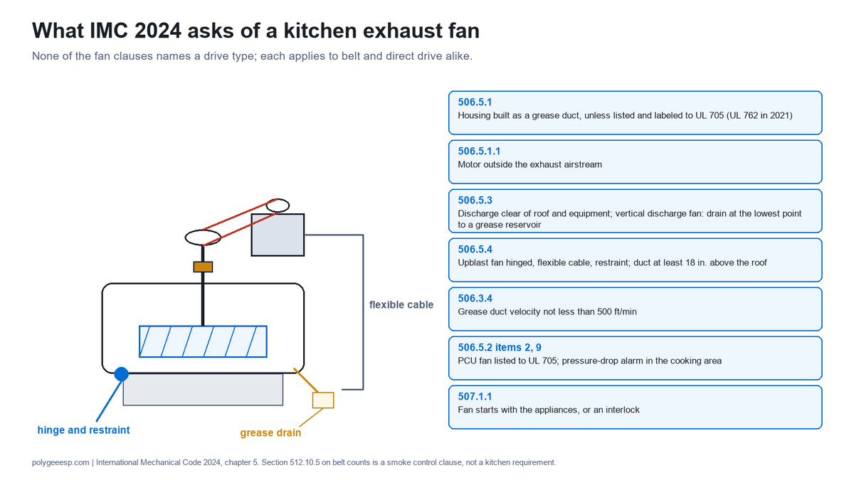
The International Mechanical Code does not choose a drive for a Type I hood exhaust fan; it sets requirements that either drive has to meet. In the 2024 IMC, Section 506.5, exhaust equipment including fans has to be of an approved design or listed for the application; Section 506.5.1 requires the fan housing to be built as a grease duct unless the fan is listed and labeled to UL 705, and Section 506.5.1.1 puts the fan motor outside the exhaust airstream. The 2021 edition gives the same exception for a fan listed to UL 762, which Greenheck’s catalog describes as the former name of UL 705 Supplement SC for restaurant exhaust.
The other fan clauses are about cleaning and grease. Section 506.5.3 asks for a vertical discharge fan to have an approved drain outlet at the lowest point of the housing, draining to an approved grease reservoir, and for the discharge not to impinge on the roof or other equipment. Section 506.5.4 asks for an upblast fan serving a Type I hood to be hinged, supplied with a flexible weatherproof electrical cable for inspection and cleaning, and restrained so that it cannot swing too far on its hinge; the grease duct extends at least 18 in. (457 mm) above the roof. Greenheck’s CUE and CUBE manual quotes NFPA 96 to the same effect on the hinge, and quotes it as asking for a drain to a readily accessible and visible grease receptacle not exceeding 1 gal (3.8 L).
| Clause (IMC 2024) | What it asks of the fan | Bearing on the drive choice |
|---|---|---|
| 506.5.1, with exception | Housing built as a grease duct, unless listed and labeled to UL 705 (UL 762 in the 2021 edition) | Listing availability depends on model and size (next section) |
| 506.5.1.1 | Motor outside the exhaust airstream | Greenheck’s catalog describes its motors as mounted out of the airstream and routes kitchen wiring through a breather tube |
| 506.5.3 | Discharge clear of roof and equipment; on a vertical discharge fan, an approved drain outlet at the lowest point of the housing to an approved grease reservoir | Applies to both; Greenheck’s CUE and CUBE are both upblast designs |
| 506.5.4 | Upblast fan hinged, with flexible cable and restraint; duct at least 18 in. above the roof | Applies to both drives |
| 506.3.4 | Grease duct velocity not less than 500 ft/min (2.5 m/s) | Any speed reduction or resistance rise has to keep it |
| 506.5.2, items 2 and 9 | Fan serving a pollution control unit listed to UL 705; a differential pressure control on the unit’s filter sections that sets off a visual alarm in the cooking area when airflow falls below design velocity | The alarm is set off when airflow falls below design velocity, whichever drive the fan has |
| 507.1.1 | Fan starts automatically with the appliances, within 15 minutes where temperature or radiant sensors start it, or an interlock prevents cooking with the fan off | Speed controls and drives are coordinated with whichever automatic control or interlock the project uses |
Greenheck’s Series C catalog gives an installation note for kitchen use: exhaust fans in kitchen ventilation must have external wiring entering through the breather tube, so that no wiring is installed in the airstream. Its motors are, in its words, carefully matched to the fan load and mounted out of the airstream. The IMC also carries a belt rule that is easy to misread: Section 512.10.5 asks belt-driven fans to have 1.5 times the number of belts the duty needs, with at least two, and motors with a service factor of at least 1.15. That clause sits in the smoke control section, Section 512, and applies to smoke control fans, not to kitchen exhaust; it is mentioned here so that it is not read as a kitchen requirement.
The published ranges: size, pressure, temperature and listing
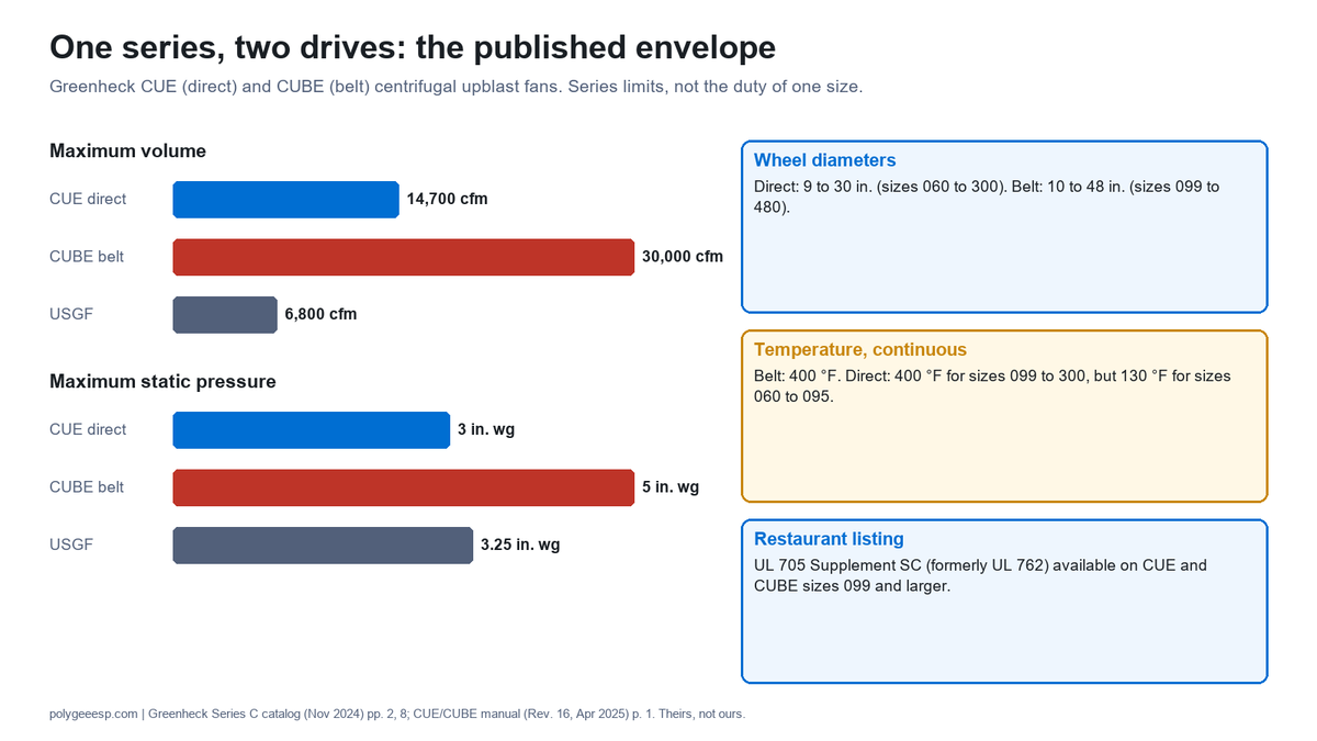
In the one manufacturer series where both drives are published side by side for this page, the belt models cover a larger duty than the direct models, and the smallest direct sizes carry a lower temperature rating and no restaurant listing. Greenheck’s Series C catalog for its centrifugal upblast fans gives the envelope: the direct drive CUE has series maximums of 14,700 cfm and 3 in. wg, the belt drive CUBE 30,000 cfm and 5 in. wg, and the steel, heavy-grease USGF 6,800 cfm and 3.25 in. wg. Those are separate limits for airflow and for static pressure across each series, not one operating point, and not the duty of any one size.
| Published figure | Direct drive | Belt drive | Source and condition |
|---|---|---|---|
| Series maximum volume and static pressure | CUE: 14,700 cfm, 3 in. wg | CUBE: 30,000 cfm, 5 in. wg | Greenheck Series C catalog, November 2024, p. 2; envelope of the series |
| Wheel diameters | 9 to 30 in. (sizes 060 to 300) | 10 to 48 in. (sizes 099 to 480) | Greenheck CUE/CUBE manual, Rev. 16, April 2025, p. 1 |
| Maximum continuous operating temperature | 400 °F for sizes 099 to 300; 130 °F for sizes 060 to 095 | 400 °F | Greenheck CUE/CUBE manual, p. 1 |
| Restaurant exhaust listing | UL 705 Supplement SC available on sizes 099 and larger | Same, sizes 099 and larger | Greenheck Series C catalog p. 8 |
| Size range, another maker | ACRU direct: 70 to 300 | ACRU belt: 100 to 490 | Loren Cook All Products catalog, January 2024, p. 8; performance limits given only as charts |
Two readings follow for a kitchen. First, the 130 °F rating and the absence of the restaurant listing on Greenheck’s smallest direct sizes mean that a small grease exhaust cannot simply take the smallest direct fan in the book; the size that carries the listing and the 400 °F rating starts at 099, where the belt range also starts. Second, the series envelope is not the whole story for direct drive. The same catalog says that CUE fans with its Vari-Green EC motors can provide all the airflow and static pressure ranges of a comparable belt drive, with 75% usable speed turndown against 30%; that is the maker’s own comparison, without the test conditions behind it, and it describes the EC versions rather than the series table above.
For a duty near either limit, the fan maker’s curve at the actual airflow and static pressure settles it. What matters for this page is that the static pressure figure has to include everything in the run, and that a treatment section in the duct moves that figure, as the next two sections show.
How a fan reaches its duty point: system curve and fan laws
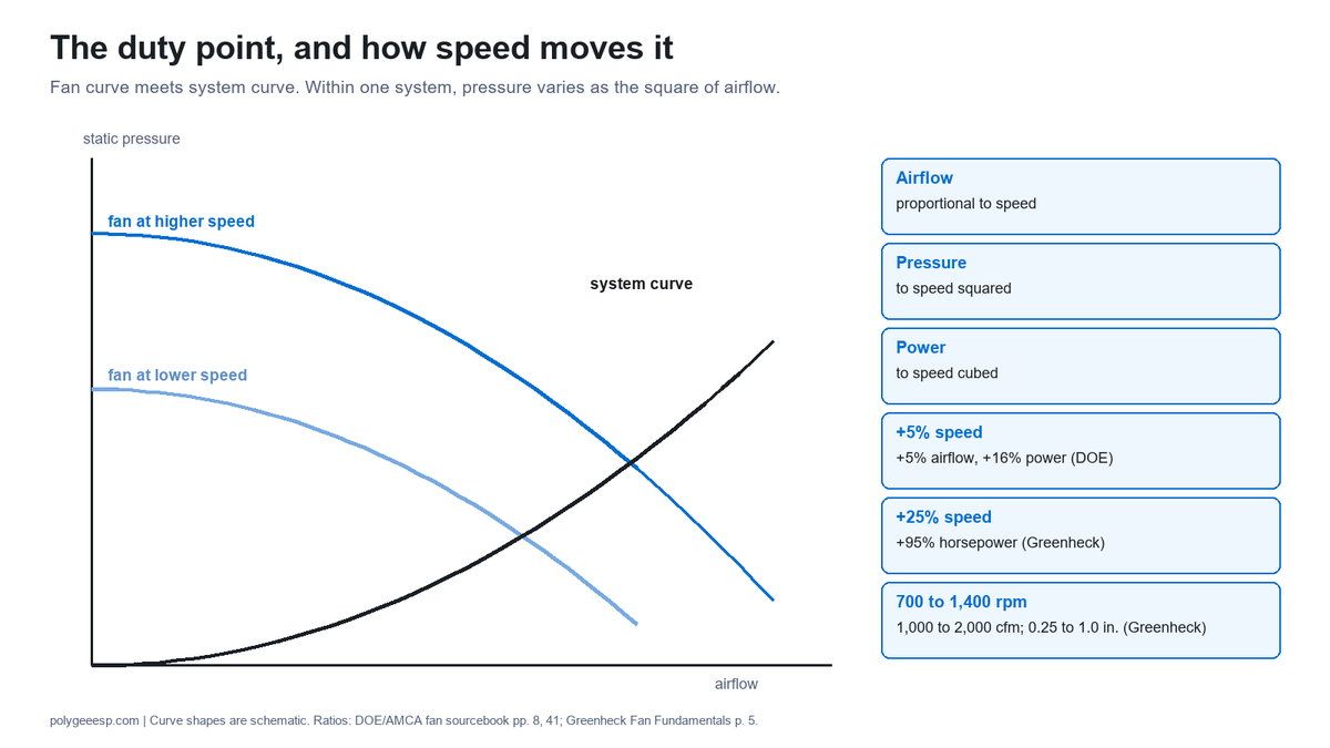
A fan runs where its own pressure curve at its present speed crosses the system curve of the duct it serves, and the drive decides how that crossing can be moved. The system curve is the static pressure the run needs at each airflow: hood, filters, duct, fittings, any treatment section and the discharge. Greenheck’s Fan Fundamentals guide gives the shape: within a system, static pressure varies as the square of airflow, so in its worked example doubling the airflow from 1,000 to 2,000 cfm raised the static pressure from 0.25 in. to 1.0 in., with the speed doubled from 700 to 1,400 rpm and the system unchanged.
The fan laws connect speed to the result. In the DOE fan sourcebook’s words, speed has a linear relationship with airflow, a second-order relationship with pressure and a third-order relationship with power, and fan speed adjustment is in general the most efficient method of airflow control. The same sourcebook works one case, about compensating for duct leaks: on an unchanged system curve, a 5 percent increase in airflow needs a 5 percent increase in fan speed and a 16 percent increase in power, though it adds that real leaks change the system curve and the power rises a little less. Greenheck’s guide states the consequence for motor selection: a 25% increase in rpm results in a 95% increase in horsepower, so a fan whose speed is likely to be raised later should be selected with a motor larger than the first duty needs.
| Change in fan speed | Airflow | Static pressure | Power | Source |
|---|---|---|---|---|
| +5% | +5% | about +10% | +16% | DOE fan sourcebook p. 41 (airflow and power); pressure by the square law on p. 8 |
| +25% | +25% | about +56% | +95% | Greenheck Fan Fundamentals p. 5 (power); pressure by the square law |
| x2 (700 to 1,400 rpm) | x2 (1,000 to 2,000 cfm) | x4 (0.25 to 1.0 in.) | about x8 | Greenheck Fan Fundamentals p. 5 worked example; power by the cube law |
The table holds on one system curve. When a section is added to the duct, or an existing section gets dirtier, the system curve itself steepens, and the fan’s new operating point and the speed and power it needs are read from the fan maker’s curves at the new duty, not scaled from the clean figure. Greenheck’s guide gives the reason a margin matters even before any change: in its example a fan recommended at 1/3 hp for an estimated 0.5 in. would need 1/2 hp if the static pressure turned out to be 0.625 in. Its static pressure guideline puts a kitchen hood exhaust at 0.625 to 1.50 in., for properly designed systems with sufficient make-up air, before the duct and any treatment are added.
This is where the two drives part. A belt fan moves along the fan laws by changing the pulley ratio; a direct fan without speed control stays near its motor speed, and its operating point slides along that one curve. That difference matters little on a run whose resistance never changes, and a great deal on one whose resistance rises between cleanings.
What an ESP adds: resistance that rises between washes
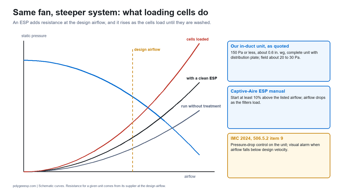
An electrostatic precipitator in the grease duct adds a section whose resistance the fan has to overcome at the design airflow, and that resistance rises as the collector cells load with oil until they are washed. Our figure for a complete in-duct unit, including the standard airflow distribution plate, is 150 Pa or less, about 0.6 in. wg, with the collector field itself in the region of 20 to 30 Pa; the figure for your airflow is the one to ask for, because the resistance of any in-duct unit depends on the airflow through it. Set beside Greenheck’s guideline of 0.625 to 1.50 in. for the hood exhaust alone, that is a share of the run that a fan selected before the unit was added did not see.
The precipitator makers read for this page describe the falling airflow in their own terms. Captive-Aire’s electrostatic precipitator manual says that the air volumes and external static pressures listed on its unit are for the middle of the operating range of the filters, that the initial air volume should be at least 10% higher than the listed figure, and that as the filters load the air volume drops; a unit set up at or below the design airflow, it warns, may lead to smoke loss at the kitchen hood as the filters load. Its start-up checklist says the minimum flow at the hood is the design volume, that flows up to 15% high are acceptable, and that starting high keeps capture as the filters get dirty.
| Document | Resistance figure given | What it says about airflow and the fan | Condition |
|---|---|---|---|
| Polygee in-duct unit (our data) | 150 Pa or less, complete unit with distribution plate; field about 20 to 30 Pa | The resistance at your design airflow goes into the fan selection; a fan can be supplied with a kitchen ecology unit and is then selected on the total static pressure of the configuration | Quoted per model at the design airflow |
| Captive-Aire electrostatic precipitator manual | Listed external static pressure at the middle of the filter operating range | Start at least 10% above the listed airflow; up to 15% high acceptable at the hood; airflow drops as filters load | pp. 11 and 64 of the manual |
| Botonair kitchen ESP manual | Not stated as a single figure | Choose a fan with capacity above the unit’s rated airflow; hold the rated airflow with a variable frequency drive or an adjustable damper at the fan outlet; fan behind the unit, under negative pressure | p. 12; commissioning to rated airflow or less, p. 17 |
| Purified Air ESP 1500E data sheet | 120 to 170 Pa | Existing extract fans often do not need to be replaced | Clean or loaded not stated |
| AirClean ESP modules | 80 Pa | Not stated | Clean or loaded not stated |
| Camfil kitchen filtration design checklist | Rises as filters in the hood and duct get dirty | A constant-flow controller on the fan holds the commissioned airflow through a variable speed drive | Applies to filtration generally |
The published figures differ by about a factor of two, and none of the three published figures says whether it is clean or loaded, so they are not a ranking; they are a reason to ask each supplier for the figure at the design airflow and the basis it is stated on. The code then catches a fan that cannot keep up. Under the 2024 IMC, Section 506.5.2 item 9 (item 8 in the 2021 edition), a pollution control unit carries an airflow differential pressure control across its filter sections, and when airflow falls below the design velocity it sets off a visual alarm in the cooking area. Section 506.3.4 keeps the grease duct at no less than 500 ft/min throughout.
A retrofit makes the point sharper, because the fan was selected for the run as it was. Our commercial kitchen ventilation system guide puts it in one sentence: the fan is selected to the design airflow at the total static pressure of the run, and a fan selected before the stage was added can deliver less than the design rate. The UK documents read for our local exhaust ventilation guide treat the same addition as a change that calls for recommissioning, with the unit’s clean resistance and the fan’s current duty point recorded as the new benchmark. The DOE sourcebook adds a warning that applies to any filter: a significant increase in system pressure from filter clogging or fouling can move a fan into an unstable region of its curve.
Getting back to the design airflow on each drive
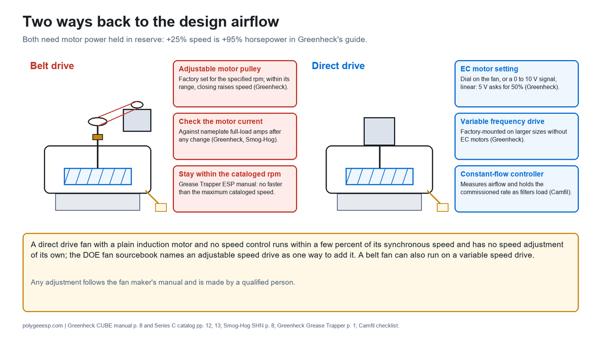
Each drive has a way back to the design airflow when the resistance rises, and both need motor power held in reserve for it. On a belt fan the way back is the pulley: Greenheck’s CUBE manual says the adjustable motor pulley is factory set for the specified rpm, that closing it increases the speed and opening it decreases the speed, that any increase in speed represents a substantial increase in the horsepower required, and that motor current should always be checked when the speed is varied. Captive-Aire’s belt upblast manual says the same about horsepower, and adds that belt tension is not to be set by changing the motor pulley, because that changes the fan speed and may damage the motor.
Makers of precipitators with their own fans describe the same move. The Smog-Hog SHN manual, for an industrial oil mist collector and cited here for the drive principle only, says that in a ducted application the blower speed is increased to compensate for the static pressure of the ducting, that the current is then measured and must not exceed the full-load amps on the motor nameplate, and that if it does, the speed is reduced at the variable pitch sheave. Greenheck’s Grease Trapper ESP manual says not to spin the fan wheel faster than the maximum cataloged fan rpm and to check the motor current after any speed change. On a belt fan, then, the limits are the pulley range of the model, the cataloged maximum speed and the motor’s current.
On a direct drive fan the way back is the motor speed, and what is available depends on the motor. The DOE sourcebook’s point applies to an induction motor without electronics: it runs within a few percent of its synchronous speed, so the duty moves along that one curve unless speed control is added. Greenheck’s catalog lists the steps above that. Speed controllers are available for shaded pole and permanent split capacitor motors on direct drive fans as an economical means of system balancing; its Vari-Green EC motors take a dial on the fan or, from 1/10 to 10 hp, a 0 to 10 V remote signal that is linear, so 5 V asks for 50%; and on larger sizes where EC motors are not offered, a factory-mounted variable frequency drive does the job for three-phase supplies.
| Way back to design airflow | Drive | What the documents say | Limit to check |
|---|---|---|---|
| Adjustable motor pulley, within its range | Belt | Factory set for the specified rpm; closing raises speed (Greenheck CUBE manual p. 8) | Pulley range; cataloged maximum rpm; motor current against nameplate |
| A different pulley ratio | Belt | A selection by the fan maker; in maintenance, the same manual allows only replacement pulleys of identical size and type | Selection by the fan maker |
| Speed controller on a shaded pole or PSC motor | Direct | For system balancing (Greenheck Series C p. 7) | Minimum duct velocity in kitchen exhaust (Greenheck CUE/CUBE manual p. 5) |
| EC motor speed setting | Direct | Dial or 0 to 10 V signal; 75% usable turndown as the maker states it (Greenheck Series C p. 12) | Motor size the EC range covers |
| Variable frequency drive | Direct or belt | Factory-mounted drive on larger direct sizes (Greenheck Series C p. 13); named by Botonair for holding rated airflow | Motor rated for drive duty; code minimum velocity |
| Constant-flow controller | Either, with a variable speed drive | Measures airflow and adjusts speed to hold the commissioned rate as filters load (Camfil checklist) | Speed and current headroom at the loaded condition |
The difference between the drives is therefore not that one can adjust and the other cannot. A pulley reset is a manual change that someone has to make; electrical speed control depends on the motor and drive actually fitted, and a variable speed drive with a constant-flow controller can hold airflow on its own, on a belt fan as on a direct fan. A direct fan with a plain induction motor and no speed control has no speed adjustment of its own, which is the case the DOE sourcebook warns about; it names an adjustable speed drive as one way to add it. On either drive the motor has to have been sized for the speed the loaded condition needs, which by the fan laws costs power faster than it gains airflow.
Belts, bearings and motors on a grease exhaust fan
The belt is the part that most separates the two drives in service, and grease and moisture shorten the intervals for the bearings and motors that both drives carry. The DOE sourcebook says that in belt-driven fans the belts are usually the most maintenance-intensive part of the fan assembly, that as belts wear they lose tension and transmission efficiency, and that contaminant build-up on belts often results in increased slippage and noisy operation; as slippage increases, it can translate directly into lower fan output. In a kitchen, that loss of output adds to the airflow already lost to a loading precipitator.
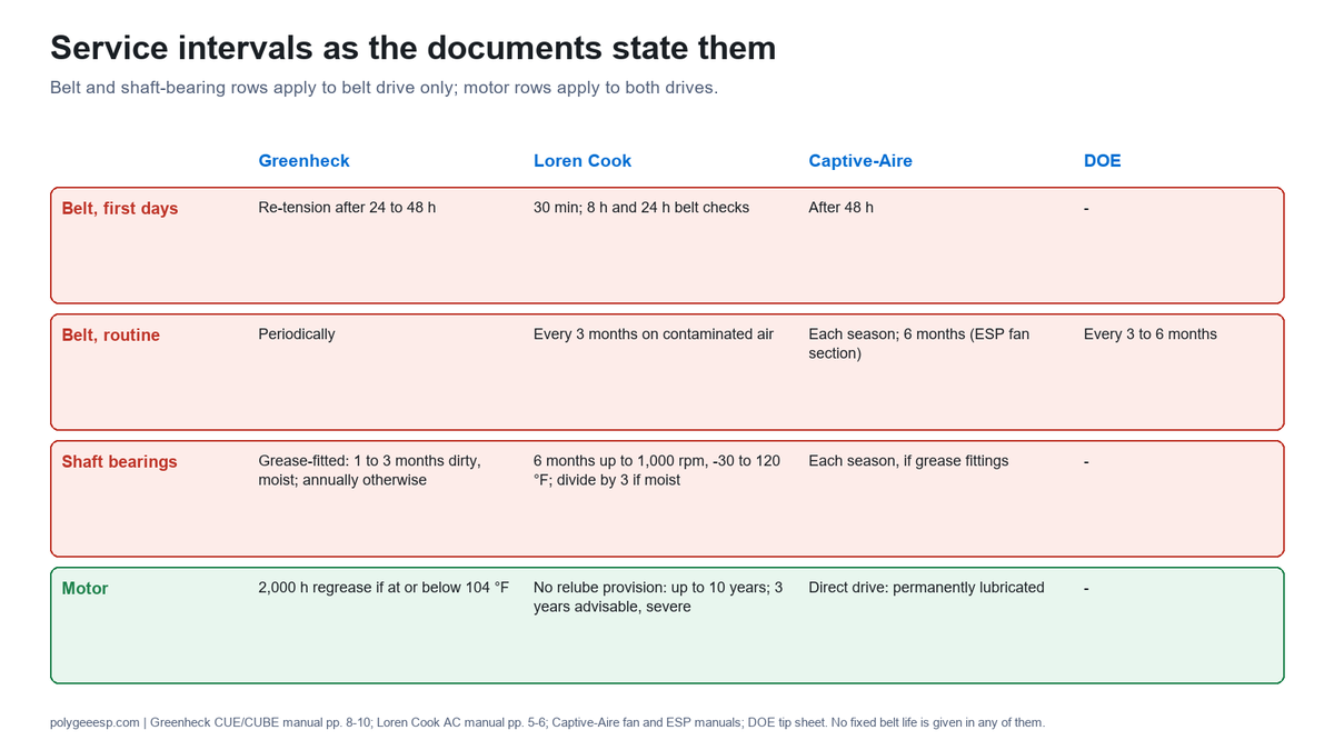
The fan manuals all call for an early tension check and differ on the routine. Greenheck asks for belt tension to be adjusted after the first 24 to 48 hours of operation, with inspections at 30 minutes and 24 hours; Loren Cook inspects at 30 minutes, 8 hours and 24 hours, and says fans exhausting contaminated air should be inspected every three months; Captive-Aire’s belt upblast manual checks tension after the first 48 hours and each season after that; and the fan section of Captive-Aire’s precipitator manual checks belt condition and tension every six months, replacing cracked, glazed or frayed belts. The DOE’s belt tip sheet puts the general figure at every 3 to 6 months after break-in.
| Item | Greenheck CUE/CUBE manual | Loren Cook AC manual | Captive-Aire fan manuals | DOE guidance |
|---|---|---|---|---|
| Belt tension, first days | Re-tension after the first 24 to 48 hours | Inspect at 30 minutes, 8 hours (alignment and tension) and 24 hours (tension) | Check after the first 48 hours | Not stated |
| Belt tension, routine | Periodically; belts stretch over time | Fans on contaminated air inspected every three months | Each season (belt upblast); every six months (precipitator fan section) | Every 3 to 6 months after break-in (tip sheet) |
| How tension is set | Sizes 180 to 480: 1/64 in. deflection per inch of span; sizes 099 to 160: just enough to prevent slip at full load | About 1/4 in. per foot of center distance, with the belt firmly pressed | 1/64 in. per inch of span (belt upblast manual); not set by changing the motor pulley | Lowest tension that does not slip at peak load; no belt dressing |
| Shaft bearings | Pillow block bearings with grease fittings: annually, or 1 to 3 months in heavy duty in dirty, hot or moisture-laden air and 3 to 6 months at 12 to 24 hours a day in heavy duty or where moisture is present; non-relubricating bearings need none in normal use between -20 and 180 °F in relatively clean air | First row of its table: 6 months up to 1,000 rpm at -30 to 120 °F; divide by three for moist or contaminated installations and by two for a vertical shaft | Each season where grease fittings are fitted | Not stated |
| Motor | Fittings: replace grease after 2,000 running hours where the motor stays at or below 104 °F; many small motors permanently lubricated | Motor bearings without provision for relubrication: up to 10 years in normal conditions; disassembly and lubrication after 3 years advisable in severe duty | Direct drive motors permanently lubricated | Not stated |
| Belt replacement | Matched sets on multi-groove pulleys; no fixed life given | No fixed life given | Replace cracked, glazed or frayed belts; replace a pulley with a worn-in shoulder | Replace all belts of a set together |
One of those rows, the motor, applies to both drives. A direct drive fan has no belt and no shaft bearings, but its motor bearings still sit above a grease duct: Greenheck’s 2,000-hour regreasing figure assumes a motor at or below 104 °F, and Loren Cook gives up to 10 years for motor bearings without provision for relubrication in normal conditions and advises disassembly and lubrication after 3 years in severe duty. A belt fan adds the belt and the shaft bearings, and Greenheck’s own lubrication table puts heavy duty in dirty, moisture-laden air at the shortest interval it lists. Where the fan and the precipitator are on the same roof or the same service round, the cleaning interval the cooking sets for the cells, covered in our electrostatic precipitator cleaning guide, is a natural point to check the fan as well.
The checks themselves are carried out by a qualified person with the fan isolated, following the fan maker’s manual for that model; this page reports the intervals the manuals give and gives no procedure.
Efficiency and noise: why the published figures disagree
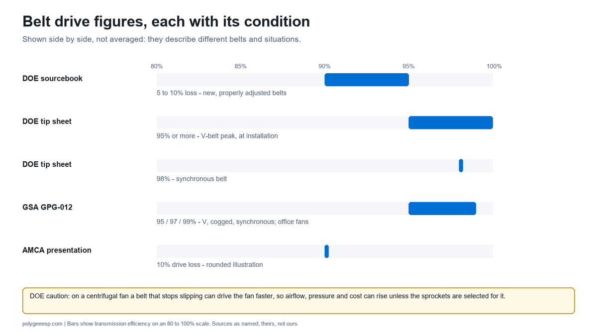
Belt drive losses are published as several different numbers because each describes a different belt in a different condition, and a figure is only usable with its condition attached. The DOE fan sourcebook says that even new, properly adjusted belts suffer losses of 5 to 10 percent, rising as the belts degrade. The DOE tip sheet on V-belts says a V-belt drive can have a peak efficiency of 95% or more at installation, can lose as much as 5% more over time if it slips for want of re-tensioning, that notched belts are about 2% more efficient than standard V-belts, and that synchronous belts run at a consistent 98%. The General Services Administration’s field test, carried out by the National Renewable Energy Laboratory, used nominal efficiencies of 95% for V-belts, 97% for cogged V-belts and 99% for synchronous belts.
| Figure | What it describes | Source |
|---|---|---|
| 5 to 10% loss | New, properly adjusted belts; more as they degrade | DOE/AMCA fan sourcebook, 2003, p. 29 |
| 95% or more peak; up to 5% further loss | V-belt drive at installation; slippage without re-tensioning | DOE tip sheet, 2012 |
| About 2% better; 98% | Notched belts against standard V-belts; synchronous belts | DOE tip sheet, 2012 |
| 95%, 97%, 99% nominal | V-belt, cogged V-belt and synchronous belt in a field test on office air handling fans | GSA GPG-012, 2014 |
| Drive loss 10% | A rounded illustration in a power-flow diagram, beside motor loss 10% and aerodynamic loss 10 to 20% | AMCA conference presentation, 2018 |
| Watt savings of 30 to 70% depending on rpm | Greenheck’s statement for its EC motor against an AC motor turned down | Greenheck Series C catalog p. 12; maker’s claim |
Two cautions come with the belt figures. The DOE tip sheet warns that on centrifugal fans, where power rises steeply with speed, a synchronous belt that stops slipping can drive the fan slightly faster, so that airflow, pressure and operating cost could actually increase unless the sprockets are selected for it; the GSA report makes the same point for constant-volume fans. And the GSA savings for synchronous belts on a variable frequency drive fan, 2.3% at 60 Hz to 20.1% at 15 Hz, were measured on air handling fans in a federal office building, not on a kitchen exhaust.
Noise is published the same way, as statements with conditions. Greenheck’s motor guide says that larger, slower belt-driven fans generate less noise for a given duty, while smaller direct drive fans turn faster for the same air delivery and generate more noise; the DOE sourcebook says that the absence of a belt lets a direct drive fan run more quietly. Both can be true, because one compares wheel size and speed and the other compares the drive train. For a kitchen the resistance itself can also matter: Camfil’s kitchen filtration checklist notes that an effective treatment system with a UL 1046 hood filter gives a relatively high pressure drop, which can result in excess fan noise where the exhaust is ventilated horizontally. The receptor-side picture, including the fan, is in our kitchen ecology unit noise guide.
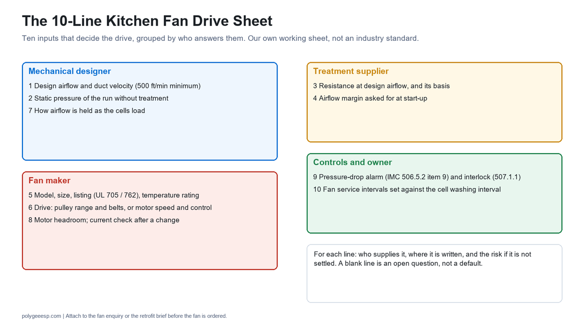
The 10-Line Kitchen Fan Drive Sheet
The 10-Line Kitchen Fan Drive Sheet records the inputs that decide the drive, and who supplies each one, before a fan is ordered for a grease duct with or without a treatment section. It is our own working sheet, not an industry standard; each line names the document or party that answers it, and a line left blank is a question still open, not a default.
| # | Line | Who supplies it | Where it is written | Risk if it is not settled |
|---|---|---|---|---|
| 1 | Design airflow at each hood, and the duct velocity it gives (not less than 500 ft/min, IMC 506.3.4) | Hood maker and mechanical designer | Hood submittal; duct schedule | A fan sized to a different airflow from the one the duct and the treatment were sized to |
| 2 | Static pressure of the run without treatment: hood, filters, duct, fittings, discharge | Mechanical designer | Fan schedule | A static pressure estimate with no basis, which Greenheck’s example shows can move the motor size |
| 3 | Resistance of each treatment section at the design airflow, and the basis it is stated on | Treatment supplier | Quotation, per model | A clean or catalog figure used where the loaded condition decides the airflow |
| 4 | Airflow margin the treatment maker asks for at start-up | Treatment supplier | Its manual; commissioning sheet | Commissioning at design airflow, then smoke loss as the cells load (Captive-Aire manual) |
| 5 | Fan model and size, listing (UL 705 or UL 762 by edition) and temperature rating at that size | Fan maker | Fan submittal | A small size without the restaurant listing or with a low temperature rating |
| 6 | Drive: belt (pulley range, number of belts) or direct (motor speed, speed control type and range) | Fan maker | Fan submittal | No way to raise speed when the resistance rises |
| 7 | How airflow is held as the cells load: pulley reset, manual speed setting, or constant-flow control | Mechanical designer with the fan maker | Controls sequence | Falling airflow is left for the pressure-drop alarm to reveal |
| 8 | Motor power headroom for the speed the loaded condition needs, and the current check after any change | Fan maker; electrician | Fan curve at loaded duty; commissioning record | A speed increase that overloads the motor (+25% rpm is +95% power in Greenheck’s guide) |
| 9 | Differential pressure alarm across the treatment (IMC 506.5.2 item 9, 2024) and the fan interlock (507.1.1) | Controls designer; treatment supplier | Controls drawing | A falling airflow with no alarm, or a speed control outside the interlock |
| 10 | Fan service intervals from the fan manual, set against the cell washing interval | Owner and service contractor | Maintenance schedule | Belt slip and cell loading taking airflow at the same time, unchecked |
Lines 1, 2, 5, 6 and 8 decide whether a given fan can do the duty at all; lines 3, 4 and 7 decide whether it keeps doing it between cleanings; lines 9 and 10 decide whether anyone notices when it stops. For a precipitator or ecology unit from us, line 3 is on the quotation and line 4 remains to be confirmed for the project, and where a fan is supplied with a kitchen ecology unit it is selected against the total static pressure of the configuration and stated on the same quotation.
Key takeaways
- The drive sets how speed changes: belt by pulley ratio, direct by the motor and whatever speed control it has; the code asks for listing, motor position, hinge, drain and interlock, not a drive type.
- Check the published range at your size: in Greenheck’s series the belt models have maximums of 30,000 cfm and 5 in. wg, the direct models 14,700 cfm and 3 in. wg, as separate limits, and the smallest direct sizes are rated to 130 °F without the restaurant listing.
- An ESP adds resistance that rises between washes: up to about 0.6 in. wg (150 Pa or less) for a complete Polygee in-duct unit as quoted, against Greenheck’s 0.625 to 1.50 in. guideline for the hood exhaust; Captive-Aire asks for at least 10% extra airflow at start-up because airflow drops as the filters load.
- Both drives can get back to design airflow, belt by pulley reset and direct by EC motor or drive, within the motor power held in reserve, and either can run on a variable speed drive; a plain induction direct drive has no speed adjustment until one is added.
- Belts and grease shorten the service cycle: re-tension early (after 24 to 48 hours in Greenheck’s manual), check on the fan manual’s interval (every 3 to 6 months in the DOE guidance), and use the dirty, moist row of the bearing table. Settle the ten inputs on The 10-Line Kitchen Fan Drive Sheet before ordering.
Frequently asked questions
- Is a direct drive or belt drive fan better for a restaurant kitchen exhaust?
- Neither is better in every case; the duty and the way the resistance changes decide it. Belt drive covers larger duties in the series compared here, with series maximums of 30,000 cfm and 5 in. wg against 14,700 cfm and 3 in. wg for direct drive in Greenheck’s catalog, and its speed can be reset at the pulley. Direct drive removes the belt, which the US Department of Energy calls usually the most maintenance-intensive part of a belt-driven fan, and with an EC motor or a variable frequency drive its speed can be changed electrically. With an electrostatic precipitator in the duct, the fan needs a way to hold airflow as the cells load; a direct drive fan with a plain induction motor and no speed control has no speed adjustment of its own; the DOE sourcebook names an adjustable speed drive as one way to add speed flexibility.
- Are direct drive fans more efficient than belt drive fans?
- Direct drive avoids the belt loss, which the DOE fan sourcebook puts at 5 to 10 percent even for new, properly adjusted belts, rising as belts wear. Other published figures are higher for the belt: the DOE belt tip sheet gives 95% or more peak efficiency for a V-belt at installation and 98% for a synchronous belt. The comparison also depends on the motor: Greenheck notes that direct drive fans below 1725 rpm need larger, costlier motors, and that its EC motors keep their efficiency as speed is turned down, a claim made by the manufacturer.
- How often should a kitchen exhaust fan belt be checked?
- Early, and then on the interval in the fan maker’s manual. Greenheck re-tensions after the first 24 to 48 hours, Loren Cook checks alignment and tension at 8 hours and tension again at 24 hours, and Captive-Aire’s belt upblast manual checks after the first 48 hours. After that: each season in Captive-Aire’s belt upblast manual, every six months in the fan section of its precipitator manual, every three months for fans on contaminated air in Loren Cook’s manual, and every 3 to 6 months after break-in in the DOE’s V-belt guidance. Cracked, glazed or frayed belts are replaced, and all belts of a set are replaced together.
- Do I need a bigger exhaust fan if I add an electrostatic precipitator?
- Not necessarily a bigger fan, but one that can deliver the design airflow at the new total static pressure, including the precipitator’s resistance as it loads. A complete Polygee in-duct unit is quoted at 150 Pa or less, about 0.6 in. wg, and Captive-Aire’s manual asks for the initial airflow to be at least 10% above the listed figure because airflow drops as the filters load. Whether the existing fan can do that is read from its curve at the new duty, with the motor current checked; the fan maker answers it, using the resistance at your design airflow from the precipitator supplier.
- Can a direct drive kitchen exhaust fan be speed controlled?
- Yes, where its motor allows it. Greenheck offers speed controllers for shaded pole and PSC motors on direct drive fans for balancing, EC motors set by a dial or a 0 to 10 V signal, and factory-mounted variable frequency drives on larger sizes. Its manual adds that minimum duct velocities must be kept in kitchen exhaust, and the 2024 IMC sets that minimum at 500 ft/min in the grease duct, so any speed reduction has to stay at or above it.
Adding an ESP or ecology unit to an existing exhaust fan?
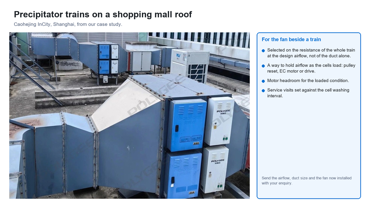
Send us the hood airflow, the duct size where the unit would go, the fan model and size now installed with its drive, and the static pressure on the fan schedule if you have it. You get back the precipitator or ecology unit configuration whose rating covers that airflow, its resistance at your design airflow stated as a complete unit, the access and drainage it needs, and the third-party test report for the model proposed, so line 3 of The 10-Line Kitchen Fan Drive Sheet is filled in before the fan maker is asked about lines 5 to 8. Where a fan is supplied with a kitchen ecology unit, it is selected on the total static pressure of the configuration and written on the quotation.
Send the airflow, duct and fan details →
The code clauses for the fan itself are set out in our commercial kitchen exhaust fan requirements guide, the duct sizing behind line 1 in our commercial kitchen exhaust duct size guide, and the figures on a precipitator data sheet, including how resistance is stated, in our electrostatic precipitator datasheet guide.
Why we write this. Comparisons of direct drive and belt drive fans are written for warehouses, barns, paint booths and industrial plants; of the four we read in full for this page, one, a duct cleaner’s blog post, takes up a grease duct, and none the treatment section that changes the duct’s resistance between washes. We make that section, not the fan, and the choice of drive is easier to make with the fan makers’ figures, the code clauses and the treatment makers’ instructions side by side. This page gives no fan selection, no maintenance procedure and no figure of ours that is not on our record.
Law is Project Manager at Polygee. Polygee, founded in 2004, manufactures the in-duct electrostatic precipitators, UV-C and activated carbon modules and kitchen ecology units named here; it does not make exhaust fans. The code text cited on this page was read in the sources listed below, and the fan, belt and treatment figures are those of the manufacturers and agencies whose documents are listed.
References & further reading
- Greenheck, Centrifugal Upblast and Sidewall Exhaust, Models CUE, CUBE and USGF (Series C catalog), November 2024: pp. 2, 4, 7, 8, 12, 13, 15 (model comparison, drives, speed controllers, UL 705 Supplement SC, Vari-Green EC motors and drive, kitchen wiring). content.greenheck.com
- Greenheck, Models CUE and CUBE Installation, Operation and Maintenance Manual, Document 471560, Rev. 16, April 2025: pp. 1, 5, 6, 8–10, 12 (wheel sizes, temperatures, kitchen duct velocity, NFPA 96 as quoted, belt tension, pulley adjustment, lubrication). content.greenheck.com
- Greenheck, FA/113-25, Motor Application Guide for Ventilation Products, 2025: pp. 1, 2, 13. greenheck.com
- Greenheck, Fan Fundamentals: pp. 1, 2, 4, 5 (pulley adjustment, static pressure guidelines, fan laws, motor margin). content.greenheck.com
- US Department of Energy and Air Movement and Control Association, Improving Fan System Performance: A Sourcebook for Industry, DOE/GO-102003-1294, April 2003: pp. 8, 15, 17, 29, 30, 33, 35, 36, 41, 51–53. energy.gov
- US Department of Energy, Motor Systems Tip Sheet, Replace V-Belts with Notched or Synchronous Belt Drives, DOE/GO-102012-3740, November 2012. energy.gov
- US General Services Administration, Green Proving Ground GPG-012, Fan Belts findings, March 2014. gsa.gov
- T. Persful, Air System Motors and Drives, AMCA conference presentation, 2018: pp. 10–13. amca.org
- Loren Cook Company, All Products catalog, January 2024: p. 8 (ACRU and ACE size ranges). lorencook.com
- Loren Cook Company, AC and VCR Installation, Operation and Maintenance Manual: pp. 5, 6 (inspections, belt tension, lubrication). lorencook.com
- Captive-Aire Systems, Centrifugal Upblast Exhaust Fan, Belt Driven, installation and maintenance manual: pp. 4, 5. captiveaire.com
- Captive-Aire Systems, Centrifugal Upblast Exhaust Fan, Direct Drive, installation and maintenance manual: p. 3. captiveaire.com
- Captive-Aire Systems, Technical Manual for Installation, Operation and Maintenance of the Electrostatic Precipitator: pp. 11, 38–39, 64 (airflow margin, fan maintenance, start-up). captiveaire.com
- Greenheck, Grease Trapper ESP Installation, Operation and Maintenance Manual, Rev. 3, July 2019: pp. 1, 9 (fan speed and motor current; drain trap sized to total system resistance). greenheck.com
- International Code Council, International Mechanical Code 2024, chapter 5 Exhaust Systems: sections 506.3.4, 506.5, 506.5.1, 506.5.1.1, 506.5.2 (items 2 and 9), 506.5.3, 506.5.4, 507.1.1; section 512.10.5 for comparison only. codes.iccsafe.org
- International Code Council, International Mechanical Code 2021, chapter 5 Exhaust Systems: section 506.5.1 exception (UL 762) and section 506.5.2 (item 8, pressure-drop alarm). codes.iccsafe.org
- Camfil, Design checklist for commercial kitchen exhaust filtration systems: constant-flow control and fan noise. camfil.com
- AirClean, Kitchen extract electrostatic precipitator modules: airflow ranges and pressure drop. airclean.co.uk
Related reading
- Commercial kitchen exhaust fan requirements: upblast, utility set or in-line, and the code clauses that govern each.
- Commercial kitchen ventilation system: the six parts of the system and how airflow and static pressure run through them.
- Electrostatic precipitator commissioning: what is measured and recorded when the unit and its airflow are handed over.
- Kitchen fire suppression system: how the hood system works and what changes when an ESP is in the duct.