

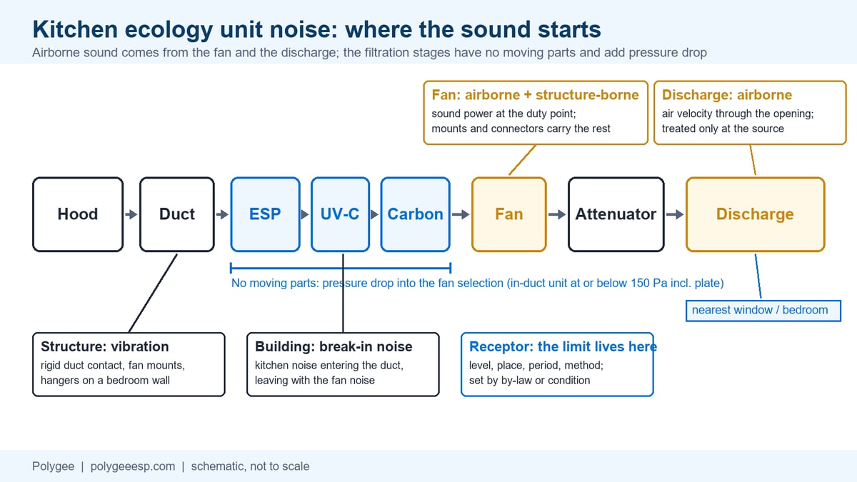
Kitchen ecology unit noise is the sound of the exhaust fan and of the air leaving the discharge; the electrostatic, UV-C and activated carbon stages inside the unit have no moving parts, so the sound of an installation starts at the fan and the discharge. What the stages add is pressure drop, and pressure drop is what sizes the fan. This page shows where each part of the sound starts, which limit applies at the point of reception, and the seven lines a quotation request needs.
The cheap question is “how many decibels is this unit?” The expensive one is a rooftop fan chosen before the filtration stages and the attenuator were added to its static pressure, running off its duty point above a bedroom, with nobody contracted to measure the result at the window.
This page helps you decide what to write about noise and vibration when you buy a kitchen ecology unit or an in-duct electrostatic precipitator for a site with neighbours: which numbers to ask for, from whom, and against which limit. It does not select the fan or size the attenuator; those belong to the ventilation contractor and the acoustic consultant on the duty point this page helps you fix. For the unit itself, its stages, its resistance and the fan offered with it, see the kitchen ecology unit page.
| Question | Short answer |
|---|---|
| What sound level should I expect from a rooftop ecology unit? | No single figure belongs to the unit. The sound power of the fan at its real duty point and the velocity of the air at the discharge set the level; the number that matters is the one at the point of reception, in the period the local limit covers |
| Why does the unit matter for noise at all? | Its pressure drop sizes the fan. Our in-duct electrostatic precipitator is rated at or below 150 Pa including the distribution plate, and that resistance, plus the attenuator, goes into the static pressure the fan is selected on |
| Who sets the limit? | The receiving side, never the nameplate: a by-law such as Vancouver’s 45 dBA at night for a source in a quiet zone received in a quiet zone, a planning condition and a BS 4142 assessment in the UK, the municipality in Dubai |
| What goes in the RFQ? | The 7-Line Ecology Unit Noise Specification Sheet: receptor and limit, hours of operation, fan sound power at the duty point, discharge, attenuator, vibration isolation, handover measurement |
| What is on Polygee’s record? | Two third-party test values, each under its own report’s conditions: 51 dB(A) on an HME hood unit, which carries its own fan (report ZY07W250333), and 49 dB(A) on an SE unit (report ZY07W250330). No noise figure for the in-duct LK-E, which has no fan |
| The unit is in and too loud: what first? | Separate the tone from the hiss and the rumble. A tone follows the fan or its motor, a hiss follows the discharge, a rumble follows the structure; the electrostatic cells have no moving parts to put them on the list |
- Where the sound comes from, and why the unit itself has no number
- Why the filtration stages change the fan, and the fan changes the sound
- Where the limit comes from: the point of reception, not the nameplate
- The 7-Line Ecology Unit Noise Specification Sheet
- When it is already installed and too loud: fan, motor, duct or ESP
- What the record shows, and what it does not
- Buyer record and key takeaways
- Frequently asked questions
Where the sound comes from, and why the unit itself has no number
An installation with a kitchen ecology unit in it makes sound in four places, and the unit’s filtration stages are not one of them. The fan makes the first part. The air makes the second, where it leaves the discharge through a louvre or a grille or simply through an open end. The structure carries the third, when the fan sits on rigid mounts or the duct is clamped to a wall that is also a bedroom wall. The building can add a fourth, when kitchen noise breaks into the ductwork and comes out of the outlet with the fan noise. The 2005 Defra guidance on the control of odour and noise from commercial kitchen exhaust systems sets out the fan, the airflow and the break-in paths in its Annex D and the structure-borne path in its Table 4.9, and its own words for the fan noise are that it is a function of the fan type, the airflow and the pressure drop, with the octave band sound power to come from the manufacturer.
The electrostatic cells, the UV-C lamps and the activated carbon bed have no moving parts. An in-duct electrostatic precipitator does not have a fan of its own; the fan is either a separate item in the ventilation package or, as on our ecology unit, available with the unit and selected on the total static pressure of the configuration. What the stages contribute to the acoustic problem is their resistance, which is why the second section of this page is about the fan.
The source that reaches the window is the one nobody specified: ask for the fan sound power and the discharge velocity on the same sheet.
| Source | Where you hear it | What sets its level | Who controls it | What it means for your specification |
|---|---|---|---|---|
| Exhaust fan | At the fan casing and down the duct to the outlet; through the roof slab when it stands on it | Fan type, airflow, static pressure at the duty point, and how far the operating point sits from the fan’s efficient region | Fan maker and ventilation contractor | Ask for octave band sound power at the real duty point, including the filtration stages and the attenuator in the static pressure |
| Discharge | At the outlet, the louvre or the grille; the nearest window hears this first | Air velocity through the opening and the free area of the opening; the 2005 Defra guidance notes that this noise rises steeply with velocity and falls as the area grows | Consultant and contractor, at the termination design | State the discharge location, free area and velocity; this source can only be treated at the source, since there is no duct after it |
| Structure-borne vibration | Inside the building, in the rooms that share a slab or a wall with the fan or the duct | Fan balance and mounting, rigid connections between fan and duct, duct hangers in contact with the structure | Contractor, at installation | Specify isolators under the fan, flexible connectors at the fan and at the unit, and isolated hangers; an outdoor airborne reading can miss this part |
| Break-in noise | At the outlet, mixed with the fan noise | Kitchen noise entering the duct through its walls and inlets; often low-frequency and harder to attenuate | Consultant | Relevant where the duct runs through a noisy kitchen with thin walls; treat it as extra fan noise in the attenuator selection |
| ESP, UV-C and carbon stages | Not as a moving-part source; as pressure drop in the fan selection | Stage resistance at the design airflow: at or below 150 Pa for our in-duct unit including the distribution plate | Unit supplier | Put the stage resistance into the fan static pressure before the fan is chosen, so the fan is not run harder later to recover airflow |
This table answers where the sound starts and who holds each lever. It does not predict a level at your window; that needs the fan’s sound power data, the duct attenuation, the discharge geometry and the distance, which is the acoustic consultant’s calculation.
What sound level should you expect from a rooftop ecology unit?
There is no typical figure, because the unit is not the source. The level at a rooftop installation is set by the fan that was selected for it and by how the air leaves; two identical ecology units with two different fans, or with the same fan at two different speeds, do not share a number. What a supplier can give you is the resistance of the stages, so that the fan is selected on the right static pressure, and, where a unit has its own fan, the sound figure measured on a tested unit under stated conditions. On our side that is one hood unit and one SE unit, described in the record section below. For the in-duct unit there is no figure, and a figure quoted for a fanless cabinet needs a question before it is used: whose fan, and at which duty point.
A 4,000 cfm ecology unit on a residential rooftop in Dubai Marina: what number should the quotation give?
Two numbers, neither of them “the unit’s decibels”. The first is the sound power of the fan offered for roughly 6,800 m³/h at the total static pressure of the hood, the duct, the stages and the attenuator, given per octave band by the fan maker. The second is the limit at the point of reception, which in Dubai is obtained from the municipality or the project’s acoustic consultant rather than from any nameplate value; the Dubai Municipality document index lists Local Order No. 61 of 1991 on the environment protection regulations, and the figure that applies to a given plot and period is confirmed against the current instrument by the authority or the consultant, not taken from this page. With those two numbers, the duct and discharge arrangement and the distance to the nearest window, the consultant can say whether the fan as offered needs an attenuator, and how much.
Why the filtration stages change the fan, and the fan changes the sound
The stages change the fan because they add resistance, and a fan that was selected without that resistance recovers the lost airflow only by running faster or by being replaced with a bigger one. The sound follows. The 2005 Defra guidance puts it in two requirements. Fans must be able to deal with the operating static pressure in the ductwork with a minimum 10 percent pressure margin, because the operating static pressure rises through a maintenance cycle. And a fan run away from its efficient duty point can be louder by up to 10 dB as well as wasteful, so a larger fan at lower speed is often the quieter choice over a smaller fan at higher speed.
For a kitchen ecology unit this means one arithmetic step that is skipped more often than it should be. The in-duct electrostatic precipitator we supply is rated at or below 150 Pa as a whole unit, including its standard distribution plate. The UV-C and activated carbon stages add their own figures, stated with the configuration. The attenuator adds its own pressure drop, the grease filters in the hood and the duct run add theirs, and the filter stages among them rise as they load. The fan is selected on that sum with the margin on top, at the design airflow, and the fan maker’s sound rating is read at that point, not at the catalogue point. Fan sound ratings are published under methods such as ANSI/AMCA Standard 301, so the duty point you give the fan maker is the point its sound data will describe.
A fan selected on the duct resistance alone runs off its point once the stages are in; a fan selected on the full static pressure with its margin, near its efficient point, is the one the guidance describes as the quieter choice, and the difference is decided before anything is bought.
| Change | Why it matters for noise | Existing fan selection still applies? | Required review |
|---|---|---|---|
| Filtration stages added to an existing duct run | Static pressure rises by the stage resistance; a fan kept as it is loses airflow, a fan sped up gains sound | No | Re-select the fan on the new total static pressure with the margin; read the sound rating at the new point |
| Attenuator added after the fan was chosen | The attenuator’s own pressure drop was not in the selection; the fan runs further from its duty point | No | Add the attenuator pressure drop to the selection and recheck airflow and sound together |
| Night operation extended | The night limit at the receptor is lower; the same fan that passed by day may not pass at night | Airflow yes, acoustic case no | Recheck against the night limit; consider a lower night speed where the hood load allows and the drive provides it |
| Filters loaded between cleanings | Static pressure rises through the maintenance cycle; the fan drifts away from its duty point | Yes, within the margin | Keep the margin the guidance asks for and the cleaning schedule the unit needs |
| Fan moved from inside the building to the roof | The outlet and the casing are closer to the receptors above; the guidance favours fans inside the building at low level where topography and ground effect reduce transmission | No | Recalculate the path to the receptor; revisit the attenuator and the mounting |
This table answers which changes send the fan selection back to the fan maker. It does not give the resistance of every stage in every configuration; those figures are stated per configuration in the quotation, and the fan supplied with our unit is selected on that stated total.
How do you add an attenuator without losing exhaust airflow?
By counting it before the fan is selected, placing it where it does not foul, and sizing it for its own face velocity. An attenuator is a pressure drop like any other component, and the Defra guidance’s Annex D says plainly that a balance has to be struck between the acoustic benefit of bends and louvres and the pressure drop they create. The same balance applies to the attenuator. Three practical consequences follow for a kitchen exhaust with filtration stages in it. First, the attenuator sits where the acoustic design puts it: the Defra guidance notes that in-duct silencers may be needed both upstream and downstream of the fan to stop fan noise radiating through the ductwork, fitted as close to the fan as a uniform airflow across the silencer allows. What a kitchen exhaust adds to that rule is grease: an absorptive lining placed upstream of the filtration stages sits in grease-laden air and can load, so the kitchen arrangement keeps the attenuator downstream of the stages, on whichever side of the fan the design needs. Second, the guidance lists the attenuator among the items that are located within the building where possible, so that the length of duct after it and the building itself do part of the work. Third, the attenuator’s pressure drop and its insertion loss per octave band are both written into the fan selection, so the fan maker selects for the airflow you need at the static pressure the system will actually present. Done in that order, the airflow is protected; done after the fan arrives, one of airflow or quiet is traded unless the fan is re-selected.
Decision rule. IF a fan has been offered for an ecology unit installation without the stage resistance, the attenuator pressure drop and the margin shown on the selection sheet, THEN the sound data on that sheet describes a different installation, BECAUSE the fan will run at a different point once the stages and the attenuator are in.
Where the limit comes from: the point of reception, not the nameplate
The limit is a number at the receiving side, for a stated period, measured in a stated way, and it comes from the by-law, the planning condition or the municipality, not from the equipment. The City of Vancouver Noise Control By-law No. 6555 is a clear example of the form such a limit takes. It defines continuous sound as sound lasting more than three minutes, or totalling more than three minutes in any fifteen-minute period. It defines the point of reception as a point in the lane or street next to the receiving property, outside that property, at the shortest distance between it and the source; where no lane, street or other public property lies between the two, it is any point outside the property line of the property the sound comes from. It defines daytime as 7:00 a.m. to 10:00 p.m. on weekdays and Saturdays and 10:00 a.m. to 10:00 p.m. on Sundays and holidays. And in section 2.1 it limits continuous sound from a quiet zone to 55 dBA by day and 45 dBA at night when received in a quiet zone. A rooftop fan serving a restaurant under bedrooms is a continuous sound source under that definition, and the number it has to meet at night, for a source and a receiver both in a quiet zone, is 45 dBA at the point of reception, not a figure on a nameplate.
Where the limit is not a fixed number, it is a method. In England the Planning Practice Guidance on noise works in observed effect levels rather than decibels and says that planning conditions can specify permissible noise levels by time of day; the method a condition then names is commonly an assessment to BS 4142:2014+A1:2019, the standard for rating industrial and commercial sound at residential receptors. The health reference behind many of these numbers is the World Health Organization’s Night noise guidelines for Europe, which set 40 dB outside the facade at night as the guideline value and 55 dB as an interim target for countries that cannot reach it in the short term.
A limit is written as a level, a place, a period and a method; a specification that carries all four can be checked at handover, and one that carries only the level cannot.
| Document | What it sets | Edition or status | What it does not settle | Buyer check |
|---|---|---|---|---|
| City of Vancouver Noise Control By-law No. 6555 | Continuous sound limits by zone and period: from a quiet zone, 55 dBA by day and 45 dBA at night when received in a quiet zone (section 2.1); from an intermediate zone, 60 dBA by day and 50 dBA at night when received in a quiet zone (section 2.2); from an activity or event zone, 60 dBA by day and 55 dBA at night when received in a quiet zone (section 2.3); measured on an approved sound meter at the point of reception | Consolidated to July 14, 2026 | Which zone a given address is in, and how the sound at the point of reception is predicted from the fan data; the exceptions in Part 4 are read for the specific premises | Read the zone schedules for the address; write the night figure into line 1 of the sheet |
| England: Planning Practice Guidance on noise, with BS 4142:2014+A1:2019 as the rating method | Effect levels rather than fixed decibels; conditions may set permissible levels by time of day; restaurants and hot food takeaways are named as developments with particular impacts | Guidance revised 22 July 2019; standard current edition 2014 with the 2019 amendment | The number itself, which the condition on your consent states | Ask the authority which method and period the condition names; brief the consultant to that |
| Defra guidance on the control of odour and noise from commercial kitchen exhaust systems, 2005 | The design expectations the 2005 text set out: control at source, acoustic design of duct, grille and termination, assessment to BS 4142, fan margin, and the submission items in its section 10: sound power or sound pressure at stated distances with the assumptions, octave band analysis where possible, hours of operation | Withdrawn by Defra on 15 September 2017; a 2018 revision by EMAQ+ is sold rather than published | Current statutory standing; it is read as reference, and the council says which text it applies | Use its section 10 list as the minimum content of your noise submission, and confirm the text the council works to |
| Singapore: NEA boundary noise limits for factory premises | For noise received at residential premises, 70 dBA by day (7 am to 7 pm), 65 dBA in the evening (7 pm to 11 pm) and 60 dBA at night (11 pm to 7 am), each over any five-minute period; lower figures for noise-sensitive premises | NEA page last updated 1 September 2024 | A restaurant is not a factory; whether these limits or another instrument apply to a kitchen exhaust is for the authority to confirm | Treat the figures as the scale the authority works in, and ask which instrument applies to the premises |
| Dubai: Local Order No. 61 of 1991 on the environment protection regulations | The emirate-level environment protection regulation listed in the municipality’s document index; its noise provisions were not read for this page | Listed in the Dubai Municipality document index | The figure for a given plot and period; it is obtained from the municipality or the consultant | Have the consultant obtain the applicable limit in writing before the fan is selected |
| WHO Night noise guidelines for Europe, 2009 | 40 dB outside the facade at night as the health-based guideline; 55 dB as an interim target | Published 2009 | Any legal limit; it is health advice, not an enforcement figure | Use it to understand why night limits sit where they do, not as a design target in itself |
This table answers what kind of limit each document sets and what it leaves to someone else. It does not cover every jurisdiction our units ship to; where yours is not listed, the pattern is the same: find the level, the place, the period and the method in the local instrument, and write them into line 1.
What does the UK odour-and-noise guidance ask for on an electrostatic precipitator system?
It asks for the same four things it asks of any kitchen exhaust, and nothing extra for the precipitator. The 2005 Defra guidance requires that, for new premises or premises under planning conditions, the system be designed to prevent an acoustic impact on the external environment, and for existing premises that it avoid statutory nuisance under the practicable-means test the guidance applies; it asks for control at source and for acoustic consideration in the duct, grille and termination design; it points to BS 4142, in the 1997 edition then current, for the assessment; and in its submission checklist it asks for the sound power or sound pressure levels of the system as a whole with the assumptions stated, an octave band analysis where possible, and the hours of operation where they differ from opening hours. An electrostatic precipitator changes two inputs to that submission, its resistance in the fan selection and the clean condition of the duct after it, and neither is an acoustic claim. Two cautions belong here. Defra withdrew the 2005 text on 15 September 2017 and its page points readers to the current guidance on nuisance smells; the 2018 revision prepared under the EMAQ+ name is sold rather than published, so this page does not quote it. Which text your council applies is a question for the council, and our UK odour control guide covers the odour half of the same submission.
Is 45 dBA at night a realistic target for a kitchen exhaust?
It is one that the documents above show, and it is met by the installation, not by the unit. Vancouver’s quiet-zone night figure is 45 dBA at the point of reception; the WHO guideline value is 40 dB outside the facade at night with 55 dB as the interim target; the Singapore night figure for residential receptors in the factory-premises regulation is 60 dBA over any five minutes. Whether a given rooftop fan meets 45 dBA at a window depends on the fan’s sound power at its duty point, the attenuation of the duct and the attenuator, the discharge velocity and area, and the distance, and that is a calculation the acoustic consultant does from the fan maker’s octave band data. What the buyer controls is whether the fan was selected on the right static pressure, whether the attenuator was in that selection, and whether the night limit was known before the order. The ecology unit’s part in reaching 45 dBA is its resistance figure, supplied early.
The 7-Line Ecology Unit Noise Specification Sheet
Seven lines in the quotation request turn “must be quiet” into something the fan maker, the contractor, the unit supplier and the consultant can each sign for. Each line has one owner. The sheet is our own framework for writing the noise part of an RFQ, not an industry standard, and it is built from the submission items in the Defra guidance, the definitions in the Vancouver by-law and the resistance figures we supply with our own units.
The 7-Line Ecology Unit Noise Specification Sheet
| Line | What to write | Who supplies it | Evidence attached | If it is left blank |
|---|---|---|---|---|
| 1 Receptor and limit | Where the point of reception is, as the applicable instrument defines it (for Vancouver, the by-law’s lane-or-street point next to the receiving property; elsewhere often the facade of the nearest dwelling), the daytime and night-time periods, the limit in dBA for each, and the instrument it comes from (by-law section, planning condition, municipality letter, or a BS 4142 assessment) | Buyer or consultant | The clause or condition in its own words | The supplier can only quote equipment data; there is no handover standard |
| 2 Hours of operation | When the exhaust actually runs, where it differs from opening hours; whether a reduced night speed is wanted | Buyer | Operating plan | The night limit is tested against the daytime case |
| 3 Fan sound power at the duty point | Octave band sound power at the design airflow and the total static pressure, where the total includes the hood filters, the duct, the stages (ours at or below 150 Pa for the in-duct unit including its distribution plate, with the UV-C and carbon figures per configuration), the attenuator and the margin; the rating method named | Fan maker, through the ventilation contractor; the unit supplier provides the stage resistance | Fan selection sheet with the sound table at that point | Catalogue sound data at a different point is read as the site figure |
| 4 Discharge | Location and height of the outlet, free area, design velocity, louvre or grille type, distance to the nearest window and air intake | Consultant and contractor | Termination drawing | The one source that cannot be attenuated downstream is left to chance |
| 5 Attenuator | Position as the acoustic design requires, upstream or downstream of the fan or both, and downstream of the filtration stages; inside the building where the layout allows; insertion loss per octave band; its own pressure drop, already included in line 3 | Acoustic consultant and contractor | Attenuator selection sheet | Airflow is lost when it is added later, or the lining sits in grease |
| 6 Vibration isolation | Isolators under the fan, flexible connectors at the fan inlet and outlet and at the unit flanges, isolated duct hangers, sealed and isolated penetrations | Contractor | Installation detail drawings | Airborne sound passes at the window and the rumble still reaches the bedroom through the slab |
| 7 Handover measurement | Who measures, where (the point of reception in line 1), when (within the period the limit covers, including the night period), with what meter setting or method, and who corrects a failure | Buyer and contractor | Commissioning and acceptance record | The first measurement is the complainant’s |
This sheet answers what to write and whom to ask. It does not fill in the numbers for you; lines 1, 2 and 4 come from your site, line 3 from the fan maker with our resistance figure in it, lines 5 and 6 from the consultant and the contractor, and line 7 from the contract. A format that can be pasted into an enquiry is also on our ecology unit specification page, where the attenuator, fire damper and ductwork are already shown as the ventilation contractor’s items.
For a Vancouver restaurant below bedrooms, what goes in the specification?
Line 1 comes straight out of the by-law, line 7 applies its measurement terms, and lines 3, 4 and 5 are where the airflow is protected. Line 1 reads: continuous sound as defined in By-law 6555, received at the point of reception as the by-law defines it, in the lane or street next to the receiving property or, where no public property lies between, outside the source property line, not to exceed the section 2.1 levels for the zone, which for a source in a quiet zone received in a quiet zone are 55 dBA in the daytime and 45 dBA at night, daytime being 7:00 a.m. to 10:00 p.m. on weekdays and Saturdays and 10:00 a.m. to 10:00 p.m. on Sundays and holidays. Line 2 states the kitchen’s actual exhaust hours, because a restaurant that cooks until midnight is in the night period for two hours. Line 3 asks the fan maker for octave band sound power at the design airflow and at a static pressure that includes the hood filters, the duct, the in-duct electrostatic precipitator at its stated resistance, the attenuator and the margin. Line 5 places the attenuator where the acoustic design puts it, downstream of the filtration stages and on whichever side of the fan the design needs, inside the building where the plan allows, and gives its insertion loss per band. Line 6 is the part the bedrooms notice: isolators under the fan, flexible connectors at both sides of the fan and at the unit, isolated hangers, and no rigid contact between the duct and the party wall. Line 7 names the contractor to measure continuous sound on an approved sound meter at the point of reception in the night period before handover. None of these seven lines changes the design airflow; the airflow is put at risk when line 3 is written without lines 4 and 5 in it. The space and access side of the same installation is on our ecology unit installation page.
When it is already installed and too loud: fan, motor, duct or ESP
The sound tells you which component to look at before anyone opens a cabinet. A steady tone that rises and falls with fan speed is the fan or its motor; a broadband hiss that is loudest at the outlet is the air at the discharge; a low rumble that is felt indoors more than heard outdoors is structure-borne; and a sound that grew over months points first to a fan drifting off its duty point as the filters loaded. The electrostatic cells, the UV-C lamps and the carbon bed have nothing that turns, so a tone or a rumble is looked for elsewhere first.
A complaint that names the ecology unit is answered by looking at the fan selected for it and the outlet it discharges through, and the record that settles it is the commissioning sheet, not the cabinet.
| Symptom | Likely cause | Evidence to capture | Safe first action | Escalation |
|---|---|---|---|---|
| Steady tone whose pitch follows fan speed | Fan blade passage or motor and drive | Fan speed, blade count, drive frequency; the sound at commissioning speed and at any reduced speed the drive offers | Have the commissioning engineer compare the readings with the fan maker’s sound data at the operating point | Fan maker; drive settings; fan replacement if the operating point is wrong |
| Broadband hiss loudest at the outlet, little change with distance from the fan | Discharge velocity through the louvre or grille | Outlet free area, design and measured airflow, louvre type; readings near the outlet and at the receptor | Have the consultant compare the measured discharge velocity with the design value | Larger termination or different louvre; this source is treated at the source only |
| Low-frequency rumble felt in rooms sharing a slab or wall; outdoor readings look acceptable | Structure-borne transmission through mounts, rigid connectors or hangers | Photographs of fan mounts, flexible connectors and hangers; any point where duct touches structure | Have the contractor check the installation against the isolation details on the drawings | Acoustic consultant for isolation design |
| Sound rose over months with no change to the fan | Filters loaded; static pressure rose; fan moved off its duty point | Current static pressure and airflow against the commissioning record; cleaning log | Return the unit to its cleaning and replacement schedule, as on our ESP replacement guide | Fan check if the sound does not return to the commissioning value after cleaning |
| Sound attributed to the electrostatic precipitator cabinet | Look first at the fan or the duct next to it; the cells have no moving parts | Readings at the cabinet, at the fan and at the outlet, noted with fan speed | Have the engineer establish whether the sound tracks fan speed or sits at the discharge | Unit supplier only if a sound stays with the cabinet and does not track the fan |
This table answers which component a symptom points to and what record to make. It does not give site procedures; readings are taken by the commissioning engineer or the contractor under the equipment manuals and the local rules, and nothing on this page replaces those.
The airflow is right but guests hear a tone: fan, motor, duct or ESP?
Start with the pitch, then the place, then the record. A tone has a frequency, and a tone that moves with fan speed is produced by the fan’s blades passing or by its motor and drive; a tone that does not move with fan speed and sits at a fixed frequency is more likely electrical or a resonance in a duct section; the electrostatic cells, which have no rotating part, are the last place to look. The place narrows it further: loudest at the fan casing points to the fan and its mounting; loudest at the outlet points to the discharge; loudest indoors on the floor below points to the structure. The record closes it: the commissioning sheet has the airflow, the static pressure and the fan speed at handover, and the fan maker’s sound table shows what the fan was expected to do at that point. If the installed static pressure is higher than the selection, the fan is running where it was not selected to run, and that is the first thing to check when a tone appeared after the filtration stages went in. Our exhaust fan requirements guide covers how the static pressure of the whole run is built up for the selection.
What the record shows, and what it does not
Our record holds two measured sound figures, and both belong to the tests that produced them. Report ZY07W250333, issued in 2025 by Beijing Zhongyan Huanneng, records 51 dB(A) on an HME integrated hood unit together with 98.1 percent purification efficiency and 116 Pa resistance; the HME carries its own fan, and the figure was measured on the unit as tested. Report ZY07W250330 from the same laboratory records 49 dB(A) on an SE unit together with 99.2 percent efficiency and 150 Pa resistance. The test conditions are on the full copies, and our test report guide explains how to read them field by field. Sound levels do not transfer between models: neither figure describes an LK-E in-duct unit, for which there is no noise figure on our record; the unit has no fan of its own, and the fan offered with it carries the fan maker’s sound rating at the duty point you specify.
Three layers of acceptance apply to noise as they apply to everything else about these units, and passing one layer does not clear the next. The first layer is equipment evidence: the stage resistance we state, and the test figures above for the two units that have them. The second is the installation: the fan selected on the full static pressure, the attenuator and the isolation fitted as drawn, the discharge built as designed. The third is the whole system in operation at the receptor, in the night period, measured as line 7 says. A unit can pass the first layer and the installation still fail the third, and the second layer is where that is usually decided. Passing one layer does not clear the next.
Buyer record and key takeaways
Before the fan for an ecology unit installation is selected, these five items are in your file.
- The limit in its own words: level, point of reception, periods and method, from the by-law, the condition or the municipality, as line 1 of the 7-Line Ecology Unit Noise Specification Sheet.
- The actual exhaust hours, including any night running.
- The resistance of every stage and the attenuator, with the margin, as the static pressure the fan maker selects on, and the octave band sound power at that point.
- The termination drawing with free area, velocity and the distance to the nearest window.
- The isolation details and the name of the person who measures at handover.
Key takeaways
- The unit has no number: the sound belongs to the fan and the discharge, not to the electrostatic, UV-C or carbon stages, which have no moving parts.
- The stages size the fan: their resistance, with the attenuator and the margin, is the static pressure the fan is selected and sound-rated on, not an afterthought once the airflow has dropped.
- The limit lives at the receptor: a level, a place, a period and a method, written down before the order, not a decibel figure asked of the supplier.
- Attenuation is placed, not added: downstream of the filtration stages, on the side of the fan the acoustic design needs, inside the building where possible, with its pressure drop in the selection, not bolted on when the complaint arrives.
- A tone is the fan, a hiss is the outlet, a rumble is the structure: the cabinet is the last place to look, and the commissioning record is the first.
Frequently asked questions
- Does an electrostatic precipitator make noise?
- The cells have no moving parts to make one. An in-duct electrostatic precipitator has no fan, so the sound an installation makes starts at the exhaust fan and at the air leaving the discharge. Where a unit carries its own fan, as the HME hood unit does, the figure on record was measured on the unit as tested: 51 dB(A) in report ZY07W250333, under the conditions stated in that report. A sound that rises and falls with fan speed is the fan; a sound that is loudest at the discharge is the air.
- Can the attenuator go before the ecology unit?
- It can be fitted upstream of the fan: the Defra guidance notes that silencers may be needed both upstream and downstream of the fan to stop fan noise radiating through the ductwork. What a kitchen exhaust adds is grease. An attenuator placed upstream of the filtration stages sits in grease-laden air and its lining can load with grease, which can change both its insertion loss and its pressure drop over time, so the attenuator goes downstream of the stages, on whichever side of the fan the acoustic design needs, inside the building where the layout allows it, with its pressure drop counted in the fan selection from the start rather than added after the fan has been bought.
- Do the 51 dB(A) and 49 dB(A) figures apply to the unit I am buying?
- Only to the two units that were tested, under the conditions written in their reports: 51 dB(A) on an HME integrated hood unit in report ZY07W250333 and 49 dB(A) on an SE unit in report ZY07W250330, both by Beijing Zhongyan Huanneng. Sound levels do not transfer between models. For the in-duct LK-E range there is no noise figure on our record, and the unit has no fan of its own; the fan offered with it carries its own sound rating from the fan maker, at the duty point you specify.
- Who measures the noise at handover?
- Whoever the specification names, at the point of reception, in the period the limit covers. The City of Vancouver by-law measures continuous sound on an approved sound meter at the point of reception it defines, in the lane or street next to the receiving property or, where no public property lies between, outside the source property line, and sets separate daytime and night-time levels; a UK planning condition names its own method and period, commonly an assessment to BS 4142. Write the measurement line into the RFQ before the order is placed; a limit that nobody is contracted to measure is settled by the first complaint instead.
Specifying a kitchen ecology unit for a site with neighbours?
Send us the design airflow, the hood and duct static pressure you already have, the limit and period from line 1, and whether you want the fan with the unit. You get back the stage configuration with its resistance per stage, the general arrangement drawing, and, where the fan is ours to offer, a fan selected on the total static pressure of that configuration, with the fan maker’s sound data at that point where the maker publishes it, with pricing on request. The attenuator and the isolation stay with your ventilation contractor, and this page tells you what to ask them for.
Send the airflow and the limit →
If the configuration is already fixed, the kitchen ecology unit page lists the stages and the sizes, and the LK-E series page covers the in-duct unit on its own.
Why we write this. The question noise raises first is a request for one number, and the honest answer is that the number belongs to a fan and a window rather than to the cabinet between them. This page says where each part of the sound starts, which document sets the limit in the places we could read in the original, and what to write so that the fan maker, the contractor and the consultant each sign for their part. It does not select fans or design attenuators, and it quotes no sound figure that is not on a report we hold.
Law manages project delivery at Polygee and prepares the factory documents that go into contractors’ submittals. Polygee, founded in 2004, manufactures the in-duct electrostatic precipitators, kitchen ESP hoods and kitchen ecology units named here and has exported to 50 countries. The by-law and guidance cited on this page were read in the sources listed below, and the BSI and AMCA standards in their catalogue entries; the two sound figures are from third-party test reports on Polygee’s record, and no sound figure is given for models without a noise test on record.
References & further reading
- City of Vancouver, Noise Control By-law No. 6555, consolidated to July 14, 2026: Part 1 definitions of continuous sound, point of reception and daytime; sections 2.1 to 2.3 continuous sound levels; Part 4 exceptions. bylaws.vancouver.ca
- Department for Environment, Food and Rural Affairs, Guidance on the control of odour and noise from commercial kitchen exhaust systems, prepared by Netcen, January 2005, reference PB10527: minimum requirements for fans and for noise control, section 2.2.3, section 4.8 and Table 4.9, section 10, Annex D. assets.publishing.service.gov.uk
- GOV.UK publication page for the same guidance, recording its withdrawal on 15 September 2017. gov.uk
- Ministry of Housing, Communities and Local Government, Planning Practice Guidance: Noise, revised 22 July 2019, paragraphs 004, 006 and 010. gov.uk
- BSI, BS 4142:2014+A1:2019, Methods for rating and assessing industrial and commercial sound. knowledge.bsigroup.com
- World Health Organization Regional Office for Europe, Night noise guidelines for Europe, 2009, ISBN 9789289041737. who.int
- National Environment Agency, Singapore, Industrial noise control: boundary noise limits for factory premises, page last updated 1 September 2024. nea.gov.sg
- Dubai Municipality, Local Order No. 61 of 1991 on the Environment Protection Regulations in the Emirate of Dubai, document index entry. dm.gov.ae
- Air Movement and Control Association International, ANSI/AMCA Standard 301, Methods for Calculating Fan Sound Ratings from Laboratory Test Data, current edition 301-22; catalogue on the ANSI webstore. webstore.ansi.org
- Beijing Zhongyan Huanneng, test reports ZY07W250333 (HME unit) and ZY07W250330 (SE unit), on Polygee’s record; the HME report is summarised on our test report guide.
Related reading
- Ecology unit installation: the straight run, the weight, the pressure and the access the same installation needs before noise is even on the list.
- Commercial kitchen exhaust fan requirements: how the static pressure of the whole run is built up for the fan selection that line 3 depends on.
- Ecology unit filters: which stages are washed and which are consumed, and why a loaded stage shows up as a louder fan.
- Commercial kitchen odour control in the UK: the odour half of the same council submission, including the EMAQ odour scoring that sits beside the noise half.