

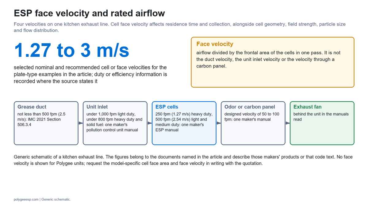
Face velocity is the speed at which exhaust air enters the cells of an electrostatic precipitator: the airflow divided by the frontal area of the cells. For a given cell, ESP face velocity sets how long a grease particle spends between the plates, which is one of the things collection efficiency depends on. Nominal and recommended figures in kitchen ESP documents run from 1.27 to 3 m/s.
These figures come from maker documents, a design checklist, a city certification list and a Shanghai technical specification; the tables record the duty or efficiency basis where the source states one. The same documents show that a rated airflow is half of a pair: several makers print more than one airflow for a unit, each with its own efficiency or duty. We manufacture in-duct electrostatic precipitators, UV-C and activated carbon modules, kitchen ecology units and the HME kitchen ESP hood. Figures attributed to other makers are taken from their published documents and describe their products, not ours; our own figures are marked as ours.
This page helps you decide what a quoted rated airflow is paired with, where your design airflow puts the cells against the published velocities, and whether the job needs a second pass in series or more units in parallel. It ends with The 8-Line ESP Airflow and Velocity Sheet. How much air the hood needs is on commercial kitchen hood CFM requirements and the duct section is on commercial kitchen exhaust duct size; neither is repeated here.
| Quick specs | Figure | Whose figure |
|---|---|---|
| Nominal ESP cell velocity by cooking duty | 250 fpm (1.27 m/s) for heavy and extra heavy duty; 500 fpm (2.54 m/s) for light and medium duty | Captive-Aire C-ESP manual |
| Maximum velocity, single pass and double pass | 1.85 m/s and 2.5 m/s, on a basis of 95% at 0.3 micron | Camfil design checklist |
| Face velocity range for one maker’s units | 2 to 3 m/s, and not higher than 3 m/s | AOS manual pages |
| Plate-type electrostatic unit | Filtration velocity 2.5 m/s or less; collector length 250 mm or more in the direction of flow; plate spacing 6 mm or less | Shanghai technical specification, 2025, informative Appendix A |
| Airflow points in the laboratory test | Rated airflow, then 80% and 120% of it | HJ/T 62-2001, clause 5.2.8 |
| One of our units at the three points | 97.4% at 80% of rated airflow, 96.0% at rated, 95.2% at 120% | Our LK120, report 2024I20-35-5322488001 |
| Resistance of our complete in-duct unit | 150 Pa or less, including the standard airflow distribution plate | Our data |
- What ESP face velocity is, and which velocity a document is quoting
- Why ESP face velocity affects what a precipitator collects
- Published ESP face velocity figures for kitchen exhaust
- A rated airflow is a pair: an airflow and the efficiency it was rated at
- Running above the rated airflow
- Running below the rated airflow
- Single pass, double pass and parallel units: three different purchases
- Even airflow across the face: transitions, straight duct and the distribution plate
- The 8-Line ESP Airflow and Velocity Sheet
- Common mistakes
- Frequently asked questions
What ESP face velocity is, and which velocity a document is quoting
ESP face velocity is the airflow divided by the frontal area of the cells, and it is one of four velocities on the same exhaust line. The US Environmental Protection Agency’s Air Pollution Control Cost Manual writes it as gas velocity equals volume flow rate divided by the frontal area, width times height, and says the frontal area “must be chosen to keep gas velocity low.” As an illustration of the arithmetic only, 1 m³/s through a face of 0.5 m² is 2 m/s. Makers do not all state which area their figure uses, so the area basis is part of the figure and has to be identified before two figures are compared.
The difficulty is that a document can print a velocity without saying where it was taken. The duct runs fast because the code asks it to: the International Mechanical Code 2021, Section 506.3.4, sets a floor of 500 feet per minute (2.5 m/s) in a grease duct serving a Type I hood. The cells run slower, and an odor panel behind them slower again. The Trion Air Boss KES manual states the consequence: “since most air ducts are designed to handle air velocities greater than the rated velocity of the air cleaner, it is necessary to properly transition any attached ducting.”
Four velocities, four sections of the same line.
| Where it is taken | Figure printed | Document | What it is for |
|---|---|---|---|
| Inside the grease duct | Not less than 500 fpm (2.5 m/s); design velocities of 1,500 to 2,500 fpm in one maker’s manual | IMC 2021 Section 506.3.4; Parker SmogHog PSG manual, 2024 | Keeping grease moving in the duct |
| At the inlet of a pollution control unit | Less than 1,000 fpm (5.08 m/s) for light duty; less than 800 fpm (4.06 m/s) for heavy duty and solid fuel | Captive-Aire pollution control unit manual | The cabinet inlet, ahead of the filter and ESP sections |
| At the ESP cells | 250 fpm (1.27 m/s) or 500 fpm (2.54 m/s), named “Nominal FPM ESP Cell Velocity” | Captive-Aire C-ESP manual | Time between the plates |
| Through an odor or carbon panel | A designed velocity of 50 to 100 fpm for an odor filter; a maximum designed velocity of 90 ft/min across each carbon filter | Parker SmogHog PSG manual; Greenheck Grease Trapper ESP manual | Contact time with the carbon |
If a quotation or a brochure gives one figure as the ESP face velocity of “the unit,” ask which of these it is. A figure of 4 to 6 m/s and a figure of 2 m/s can both be honest if one is taken at the connection and the other at the cell face. How the duct section is chosen against the 500 fpm floor is worked through on our exhaust duct size page.
Why ESP face velocity affects what a precipitator collects
Collection depends on plate area per unit of airflow and on the time a particle spends between the plates. The EPA manual reduces the theory to the Deutsch equation: the fraction of particles that escape equals exp(−w × SCA), where w is the effective migration velocity of the particles toward the plates and SCA, the specific collection area, is the collecting plate area divided by the gas flow. For a fixed plate area, more airflow reduces the SCA; in the Deutsch relation that increases the escaping fraction if the effective migration velocity is held constant.
The plate-type kitchen precipitators discussed on this page have separate charging and collecting sections. That is what two-stage means; it does not mean two passes in series. The EPA manual describes the two-stage precipitator as a series device with the ionizer ahead of the collector plates, “generally used for gas flow volumes of 50,000 acfm and less” and applied to “submicrometer sources emitting oil mists, smokes, fumes, or other sticky particulates.” A California Air Resources Board research report, describing the two-stage design, states that charging reaches saturation in 0.01 seconds or less and that precipitation of the charged particles takes 1 to 10 seconds in the precipitators it covers. Those are industrial figures and not kitchen design values. A higher velocity shortens the time available in both the charging section and the collecting section. The EPA manual adds that for a given field the migration velocity “is usually at a minimum for particles of about 0.5 µm diameter.” The cooking studies in the next paragraph report number and mass distributions, which are different bases.
Cooking emissions sit in the size range where this matters. A review of cooking emissions in Atmospheric Environment reports number distribution modes “generally in the range of 20 to 100 nm,” and a University of California, Riverside study of commercial cooking for the South Coast Air Quality Management District found a mass peak at 0.17 µm for each cooking combination it tested. In a laboratory study of a two-stage air cleaner of a kind installed in offices and hospitals, published in Indoor Air in 2002, total particle-number collection efficiency for environmental tobacco smoke was 95.2% at 472 L/s and 71.8% at 944 L/s; the study also reported an efficiency minimum between 0.1 and 0.45 µm. That unit was a building air cleaner, the aerosol was not cooking fume and the efficiency was counted by particle number, so the percentages do not transfer to a kitchen unit or to a mass-based fume test. In that tobacco-smoke test, doubling the airflow reduced total particle-number collection efficiency by 23.4 percentage points.
The formula is a first estimate and its authors say so. An EPA training course on precipitator plan review states that operating parameters “can cause the results to be in error by a factor of 2 or more” and that the equation “should be used only for making preliminary estimates.” One of the things it assumes is that the gas flow is uniform everywhere across the precipitator, which is why the last technical section of this page is about the inlet. The ASHRAE Handbook chapter on air cleaners puts the design point in one sentence for the same plate-type technology: air velocity, ionizer field strength, cell plate spacing, depth and plate voltage “must match the application requirements,” giving contaminant type, particle size, volume of air and required efficiency as examples. The mechanism itself, from ionizer to plate, is on what an electrostatic precipitator is.
Published ESP face velocity figures for kitchen exhaust
The documents read for this page that name the cell or the face print nominal and recommended velocities from 1.27 to 3 m/s, and the table records the duty or efficiency basis where the source states one. A figure for impaired performance and a figure for honeycomb units are identified separately. They are not one standard. Two are maker manuals, one is a filter maker’s design checklist, one is a regulator’s record of test conditions and one is an informative appendix to a city specification.
Read the third and fourth columns before comparing any two rows.
| Document | Velocity printed | Section it names | Duty or efficiency basis stated |
|---|---|---|---|
| Captive-Aire C-ESP manual, model number explanation (the Gaylord ClearAir RSPC-ESP manual carries the same coding) | 250 fpm (1.27 m/s); 500 fpm (2.54 m/s) | “Nominal FPM ESP Cell Velocity” | Heavy and extra heavy duty cooking; light and medium duty cooking |
| Camfil design checklist for kitchen exhaust filtration systems | Single-pass ESP maximum 1.85 m/s; double-pass ESP maximum 2.5 m/s. Separately, the checklist describes single-pass filtration systems as operating below 1.85 m/s and gives 650 L/s per 600 × 600 mm area | Velocity through the ESP, and through the filtration system | Higher velocity “likely results in efficiency below 95% at 0.3 micron” |
| AOS ESP manual pages, face velocity and installation guidelines | 2 to 3 m/s; not higher than 3 m/s; at 4 to 5 m/s “efficiency is compromised significantly” | Face velocity through the unit | No particle size or test method stated |
| Airclean data sheet AC10.5 | Maximum recommended 2.5 m/s | Face velocity | Single pass stated at 95% without a particle basis |
| Marvel Ventilation specification table | 2.2 to 2.25 m/s | “Speed through filters” | 96% single pass, without a particle basis |
| AAF Asia product page | 500 fpm (2.54 m/s) | Not stated | 95% for 2 to 5 micron particles, tested to EN 779 |
| Shanghai Technical Specification for Catering Fume Pollution Control, 2025, Appendix A (informative) | Plate type: 2.5 m/s or less. Honeycomb type: 6.0 m/s or less | Filtration velocity (our translation of the Chinese term) | PM2.5 removal of 90% or more; plate spacing 6 mm or less and collector length 250 mm or more for the plate type |
| New York City DEP list of certified emission control devices for under-fired char broilers, updated November 2024 | Air Scrubbers SA series, single-pass ESP: 283 ft/min (1.44 m/s), tested at 1,600 cfm. CaptiveAire PCU-HE-ESP-ESP, a MERV 15 filter and two ESP sections: 402 ft/min (2.04 m/s), tested at 2,515 cfm. Gaylord RSPC: maximum filter velocity 400 ft/min (2.03 m/s) | The list prints the ESP face or active area per pass or per stage, in square feet, beside each figure | Certification test conditions, and one listed maximum filter velocity, for char broiler exhaust; not recommendations |
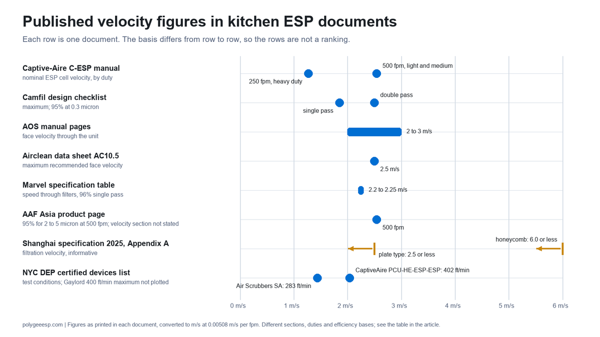
Three readings follow from the table. First, the lowest figure is attached to the heaviest duty: the manual that prints 250 and 500 fpm halves the cell velocity for heavy and extra heavy duty cooking. Second, the plate-type and honeycomb-type figures in the Shanghai appendix differ by more than a factor of two because they describe two constructions, so the higher one does not transfer to a plate cell. Third, the percentages cannot be compared directly: the rows use different particle-size bases, and some sources do not state their measurement basis.
Two association articles sit close to the same range. An article in the April 2018 issue of AIRAH’s Ecolibrium states that single cell ESPs are designed around 1.8 to 2.0 m/s and advises keeping the velocity below 2.0 m/s, preferably 1.85 m/s. An article published by New Zealand’s HVAC&R Centre gives 2 m/s. Both refer to a published curve from a 1961 experiment on a coal-fired power station precipitator, and both are articles by practitioners, so they are advice and not a standard. One product page prints 4 to 6 m/s as its standard calculation without naming the section, and says in the next lines that 2.5 to 3 m/s gives higher cleaning efficiency; without the section it cannot be placed in the table.
The same figures appear as background on our ESP arcing page, where the question is a fault and not a selection.
A rated airflow is a pair: an airflow and the efficiency it was rated at
A rated airflow means something only with the efficiency, the test method and the particle basis it was rated at. Several makers print more than one airflow for the same unit.
How five makers’ documents relate airflow to efficiency or cooking duty.
| Document | The unit | Lower airflow, and what it is paired with | Higher airflow, and what it is paired with |
|---|---|---|---|
| Trion Air Boss ATS manual, capacity table as reproduced on a manual archive | ATS-2 | 1,375 cfm at 95%, face velocity 374 fpm (1.90 m/s) | 1,500 cfm at 90%, face velocity 406 fpm (2.06 m/s) |
| Smog-Hog PSG brochure, distributor edition of 2019 | PSG-11, one cell | 1,250 cfm at 95% DOP | 1,480 cfm at 90% DOP; fractional efficiency at 0.3 to 1.0 micron |
| Airclean selection table, web page | 1H × 1W | Flow rate up to 0.69 m³/s | Maximum capacity 1.27 m³/s; “Running at max capacity will result in drop of efficiency to 85%” |
| Marvel Ventilation specification table | Its one-cell unit | 450 L/s, recommended for high efficiency filtration on heavy cooking | 950 L/s, recommended maximum for light cooking |
| Air Quality Engineering, article on PCU efficiency | One full size cell | A lower cfm per cell where a higher efficiency is required | About 2,000 cfm per cell as its sizing figure |
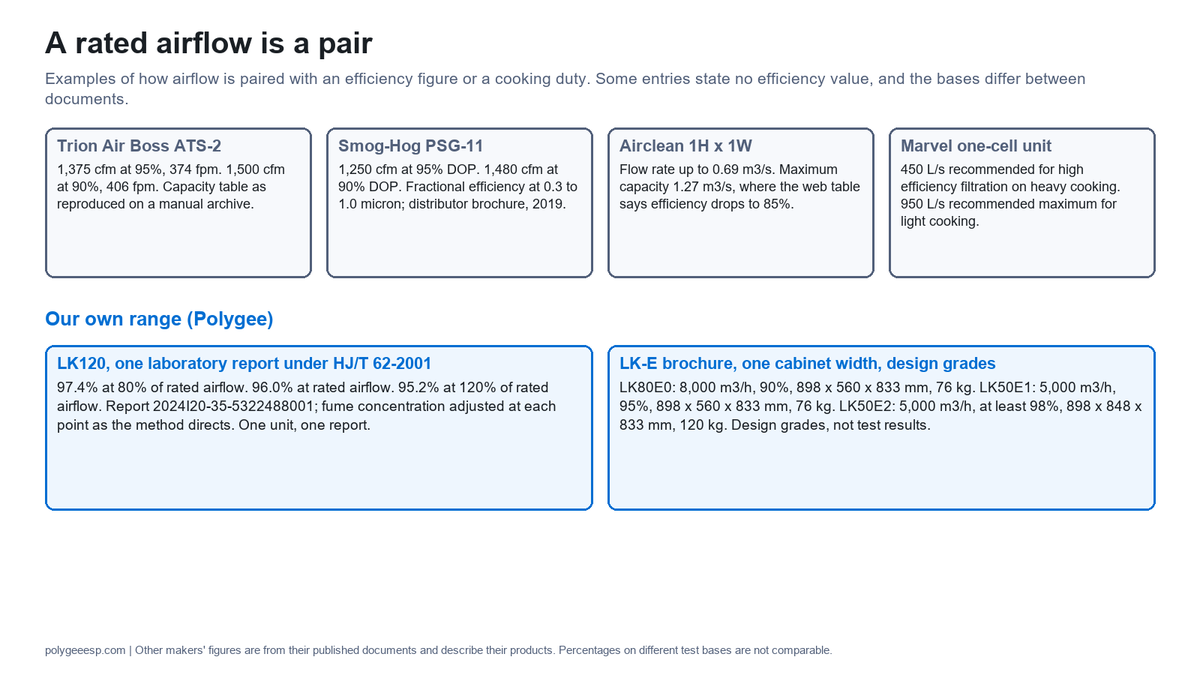
The Trion table prints two more rows for the same model, 1,600 cfm at 95% and 433 fpm, and 2,000 cfm at 90% and 540 fpm. The reproduced page flattens the headings; from the order in which they appear we read the first pair as a DOP basis and the second as an ASHRAE basis, and the original page was not available to confirm it. If that heading assignment is correct, the ATS-2 is listed at 95% under two rating methods with two airflow figures; the reproduced table does not establish that the test method is the only difference.
The Chinese laboratory method is built on the same idea. HJ/T 62-2001, the test regulation for cooking fume control equipment, assesses removal efficiency at the rated airflow under clause 4.2.1, and clause 5.2.8 then changes the airflow to 80% and 120% of the nameplate rating and measures again. Its Table 2 applies the same minimum, 60%, 75% or 85% by size class, at all three points. The standard covers equipment of 2,000 to 20,000 m³/h and requires the nameplate to carry the airflow, the efficiency and the equipment resistance. It uses rated airflow without separately defining the term and does not specify a plus-or-minus tolerance on that rating.
Our own range shows the same thing twice
The first place is a test report. One of our LK120 units was measured by one laboratory under HJ/T 62-2001 at the three airflow points.
| Airflow point | Efficiency recorded | Report |
|---|---|---|
| 80% of rated airflow | 97.4% | 2024I20-35-5322488001, SQEP, CMA 180912110235; one LK120; fume concentration adjusted at each point as clause 5.2.8 directs |
| Rated airflow | 96.0% | |
| 120% of rated airflow | 95.2% |
The result moves in the direction the theory gives and by less than the teaching example above would predict from 96.0%. It is one unit in one report, the report does not explain the size of the steps, and it is not a license to run any unit at 120%: the figure a buyer may rely on is the one at the airflow the unit will see. The full reading of that report is on how to read an ESP test report. The highest figure in the LK range, up to 97.6%, was read on an LK160 at 16,000 m³/h in CMA-accredited third-party report ZY05W230298, and is quoted with its model and its airflow for the same reason.
The second place is the LK-E brochure. It publishes three design efficiency grades, and the rows for one cabinet width read as follows.
| Model | Grade and design efficiency | Rated airflow | Outside dimensions (mm) | Flange (mm) | Weight | Equipment resistance |
|---|---|---|---|---|---|---|
| LK80E0 | E0, 90% | 8,000 m³/h | 898 × 560 × 833 | 651 × 614 | 76 kg | 31 Pa |
| LK50E1 | E1, 95% | 5,000 m³/h | 898 × 560 × 833 | 651 × 614 | 76 kg | 23 Pa |
| LK50E2 | E2, at least 98% | 5,000 m³/h | 898 × 848 × 833 | 651 × 614 | 120 kg | 34 Pa |
The E0 and E1 rows have the same outside dimensions, flange and weight and two rated airflows, 8,000 and 5,000 m³/h, with the lower airflow carrying the higher design grade and the lower resistance. The E2 row keeps the airflow and the flange of the E1 row; its second outside dimension goes from 560 to 848 mm and its weight from 76 to 120 kg. Across all eleven E0 and E1 pairs with matching outside dimensions, our calculation from the brochure rows puts the E1 airflow at 60% to 75% of the E0 airflow; matching weight is not a condition of that comparison. These are design grades, not test results, and the brochure does not print the cell face area, the plate spacing or what is inside each cabinet. We therefore do not publish a face velocity for these models here; ask for the model-specific cell face area and face velocity in writing with the quotation. The rows associate different design grades with different rated airflows or cabinet dimensions. They do not show that reducing the airflow through an installed unit changes its design grade. On our ESP datasheet page the same table is read the other way round: the same airflow in another grade is a different cabinet.
The practical test for any quotation is one question: at what airflow, by what method and on what particle basis was the efficiency next to this rated airflow obtained? A local authority checklist in England separately asks for a product data sheet showing the dimensions of the ESP and its flow rate rating; that entry does not specify an efficiency test method or a particle basis.
Running above the rated airflow
Running above the rated airflow can reduce the fraction collected, and two Shanghai documents require the rated treatment airflow to be at least the actual airflow. The Shanghai emission standard DB 31/844-2014, clause 4.3, requires that the rated treatment airflow of the purification equipment be not less than the actual treatment airflow and that the equipment be interlocked with the exhaust fan (our translation), and the city’s 2025 technical specification repeats both points in clause 6.1. Hong Kong’s Environmental Protection Department puts the design basis as “peak load conditions (i.e. the worst case scenario).”
Makers write the symptom into their troubleshooting. The Parker SmogHog PSG manual lists, against “System efficiency is poor. Smoke is discharging to the atmosphere,” the cause “Air volume (ACFM) is not within specifications.” The AOS page says that at 4 to 5 m/s efficiency “is compromised significantly.” The Botonair kitchen ESP manual gives the instruction that follows: with an airflow measuring device, the airflow is adjusted so that the actual airflow handled by each unit “is equal to or less than the rated airflow capacity.”
There is a second mechanism in the general literature. The EPA manual notes that a precipitator collecting dry material risks continuous reentrainment “if the gas velocity becomes too large,” an effect it calls independent of SCA. The velocity limits it gives, about 1.5 m/s and 1 m/s, are for fly ash in large power station precipitators and are not kitchen figures; the AIRAH article applies the same idea to kitchen units as scouring of collected particles at high velocity.
A unit ends up above its rating in ordinary ways, none of which appears on its nameplate:
- The fan was selected with a margin and not set back. The Botonair manual asks for a fan with more capacity than the rated airflow of the equipment and, in the next sentence, for a frequency drive on the fan or an adjustable damper at the fan outlet so that the equipment works at the rated airflow. The margin and the setting belong together.
- A hood or an appliance was added to the line. If the addition increases the required airflow without a corresponding change in ESP capacity, the unit may be overloaded.
- Units in parallel share one fan unevenly. The same manual asks that the airflow reaching each unit approximate the proportion of each unit’s rated capacity. A header that favors one branch overloads that unit while the total looks right.
- The air does not reach the whole face. The total airflow can be within the unit’s rating while part of the cell sees a higher local velocity; the section on even airflow below covers this case.
One sentence in an older manual points the other way and is easy to misread. The Captive-Aire C-ESP manual says the initial air volume “should be at least 10% higher than the listed CFM.” It is that manual’s start-up instruction for its own unit, given in the context of filters that load and reduce the airflow over time; it is not a general allowance to exceed another unit’s rated airflow.
The airflow a unit is running at is a measured number from the balancing report, and comparing it with the rating is a step in ESP commissioning. Adjusting it is work for the commissioning contractor under the unit manual and the fan maker’s instructions.
Running below the rated airflow
For a fixed cell, a lower airflow gives more residence time; problems appear upstream if the system airflow is too low for hood capture or for the duct. On the cell alone, within the range these documents cover, less air means more time: Air Quality Engineering recommends a lower cfm per cell where a higher efficiency is required, and our LK120 read its highest figure at the 80% point. The AIRAH article adds a limit at the low end, where it says turbulence in an energized field with low airflow reduces the effective migration velocity.
The limits are set elsewhere on the line. Under IMC 2021 Section 506.3.4 the minimum in a Type I grease duct is 500 fpm, subject to its stated exception; reducing the airflow crosses that minimum only when the resulting duct velocity falls below it. Two articles from one supplier describe the result, grease dropping out upstream of the unit and settling in the ductwork, and another supplier’s article notes that with much less airflow than expected the exhaust system may not capture contaminants at the hood. The IMC also treats low airflow at the unit as an alarm condition: Section 506.5.2, item 8, requires an airflow differential pressure control across the filter sections of a pollution control unit, with a visual alarm in the cooking area “when the airflow is reduced below the design velocity.” A study of a commercial kitchen exhaust system in Tianjin, published in Applied Sciences in 2022, describes the same trade: 11,726 m³/h was the measured operating airflow, about 65% of the rated air volume, and the authors’ simulations at that airflow predicted purification efficiency that met the standard requirements together with a cooking area beyond the comfort range and pollutant spillage along one wall.
Our selection advice is to keep the exhaust line at its required design airflow and to choose a unit whose documented performance covers that airflow, with any margin confirmed for the model. Where the fan speed varies with the cooking load, the floor of the speed range is decided by the hood and the duct; that side is on our demand control kitchen ventilation page.
Single pass, double pass and parallel units: three different purchases
A second pass in series can be selected for higher efficiency or, where the documented rating supports it, for more airflow at a stated efficiency; parallel cells or units add frontal area. The Parker manual defines the term: air that flows through one set of cells makes a single cleaning “pass,” and where an application requires it, “multiple passes can be placed in series in the direction of airflow.” The Gaylord manual describes a double pass as a second row of ESP cells.
The documents use the second pass in two different ways, and a quotation should say which.
| What is bought | What the documents print | What it changes | What it does not change |
|---|---|---|---|
| A second pass for efficiency at the same airflow | Airclean: single pass 95%, and a double pass recommended “to achieve a 99% efficiency” where efficiency is critical, such as low level extract. Botonair: single pass at least 90%, double pass at least 98.7%, at rated airflow and 60 °C. Marvel: 96% single pass, 99% in a double pass arrangement | The escaping fraction at the design airflow; length, weight and resistance of the train | With the same frontal area in each pass and the same airflow, the face velocity is unchanged |
| A second pass for more airflow at the same efficiency | Camfil: maximum 1.85 m/s single pass and 2.5 m/s double pass on the same 95% at 0.3 micron basis. Air Quality Engineering: a double pass set can “push the airflow up about 37% to 2,750 CFM”; its text does not state the efficiency value that goes with that figure | The airflow one face is rated for, by about a third in these two documents | These two examples do not show a doubling of airflow; a second pass alone does not establish a twofold airflow rating |
| Units in parallel or stacked | AOS: units stacked and bolted together to increase airflow. Airclean: for airflows larger than those stated, multiple units in parallel. Air Quality Engineering: more cells to hold 2,000 cfm or less per cell | The face area, so the airflow at a given face velocity | The efficiency of each cell |
The middle row is the one that goes wrong. The AIRAH article says it directly: double-pass ESPs “do not necessarily allow you to double the airflow and maintain 95 per cent efficiency at 0.3μm,” and it advises enlarging the face area to bring the velocity down in preference to placing single-cell units in series. From 1.85 to 2.5 m/s is an increase of 35%, and Air Quality Engineering’s figure is 37%.
Duty decides when a second pass is specified. Greenheck’s standard Grease Trapper ESP unit has two ESP modules and its solid fuel unit has three. Halton recommends double pass ESP modules for extra heavy duty applications such as solid fuel cooking and for odor-critical sites, and AOS recommends the double pass configuration for heavier cooking. The solid fuel case is on our solid fuel cooking and the ESP page, and discharge near windows or at low level on ecology unit low-level discharge.
On our own range, more airflow than one unit is rated for is met with units in parallel or in stacked layers until the rated airflow is not below the collected airflow, the arrangement described for multi-tenant risers on our food court exhaust page. A higher design grade at the same airflow is met by the grade tables above. Parallel or stacked units are our documented way of adding capacity. Any proposal for two units in series needs model-specific confirmation and a stated resistance for the complete train; a complete in-duct unit of ours, with its standard airflow distribution plate, is rated at 150 Pa or less.
Even airflow across the face: transitions, straight duct and the distribution plate
The rated figure assumes the air arrives evenly across the whole face, and the documents say how to arrange that. A face velocity is an average. If a short transition or an elbow sends most of the air through one side of the cell, that side runs above the average and the other side runs below it, and the EPA course lists uniform flow among the assumptions the efficiency formula depends on.
What the documents ask for at the inlet and outlet.
| Item | What is printed | Document |
|---|---|---|
| Distribution over the face | The total air volume is to be “uniformly distributed across the entire face area of the unit”; a perforated plate and metal mesh filters provide resistance for even distribution | Trion Air Boss KES manual |
| Transition | A contraction ratio of 1 in 3, approximately 20 degrees, where possible; turning vanes, air baffles or other means where space prohibits | Trion Air Boss KES manual |
| Transition to the unit | Ducts transition to the full size of the unit’s inlet and outlet openings | IMC 2021 Section 506.5.2, item 13 |
| Straight duct | At least 3 duct diameters of straight duct at the inlet and at the outlet of the unit; no flexible ductwork or square elbows | Captive-Aire pollution control unit manual |
| Straight duct | Smooth reducers at inlet and outlet, joined to smooth ducts at least 4 times the diameter of the reducers in length | Botonair kitchen ESP manual |
| Distribution plate | A perforated airflow divider at the air inlet, to stabilize the velocity and distribute the gas to all zones of the cells | Botonair kitchen ESP manual |
| Inlet plenum | Inlet plenums with baffle filters or aluminum media “to promote even air distribution across subsequent system components” | Parker SmogHog PSG manual |
| Connections to second-stage equipment | Reducers and guide fittings at the connection between the purification equipment and the duct, to reduce the effect of disturbed airflow | Shanghai technical specification, 2025, clause 6.1.1.5 |
| Duct approaches | Arranged “so that airflow is distributed uniformly over the face area”; panel prefilters also help distribute airflow | ASHRAE Handbook, Systems and Equipment, 2016, chapter 29 |
| Fan position | The equipment works under negative pressure, with the fan installed behind it; one data sheet places units “upstream of the extraction fan” | Botonair kitchen ESP manual; Purified Air data sheet, 2007 |
Use the installation document for the model being installed together with the applicable code and approval requirements, and do not substitute another maker’s straight-duct figure. Two points are worth keeping apart. The diffuser plates described in the EPA manual, with holes of 5 to 7 cm and 50 to 65 percent open area, belong to power station precipitators and are not a kitchen specification. And IMC 2021 Section 506.3.4 exempts from its velocity minimum only transitions that connect ducts to differently sized or shaped openings in hoods and fans, that are no longer than 3 feet and that are designed to prevent the trapping of grease; the text does not expressly extend that exception to connections at an ESP, so the designer of the line reads a long transition against the code in force.
Our in-duct units are supplied with an airflow distribution plate as standard, and the 150 Pa figure for the complete unit includes it. Ask for the model-specific straight lengths, clearances and installation documents with the quotation; the space a three-stage train takes is on ecology unit installation.
The 8-Line ESP Airflow and Velocity Sheet
Eight lines turn the sections above into a record that goes with an enquiry and comes back with a quotation. It is our own framework, not an industry standard. No line has a default value; a line that cannot be filled is the finding.
| # | Line | Who supplies it | If it is left blank |
|---|---|---|---|
| 1 | Design airflow at the unit for the documented peak concurrent operating condition, and the document it comes from | Mechanical engineer or hood schedule | The unit is sized on a guess, and the velocity in line 4 cannot be worked out |
| 2 | Cooking duty on the line: appliances, fuel and hours | Operator or kitchen designer | A light-duty velocity is applied to a heavy-duty line |
| 3 | Rated airflow of the model proposed, with the efficiency it is paired with, the test method and the particle basis | Unit maker | The efficiency claims in two quotations cannot be compared on a common basis |
| 4 | Cell face area per pass, and the face velocity at the airflow in line 1 | Unit maker | The ESP face velocity cannot be placed against the published 1.27 to 3 m/s |
| 5 | Number of passes in series, and whether the second pass is there for efficiency or for airflow | Unit maker | If a second pass is quoted, it is assumed to double the airflow |
| 6 | Number of units in parallel, the rated airflow of each, and how the airflow is divided between them | Unit maker and duct designer | One unit is overloaded while the total is within the rating |
| 7 | Inlet and outlet arrangement: transition, straight length available, distribution plate, fan position | Duct designer, against the unit maker’s installation document | The average velocity is right and the distribution is not |
| 8 | Measured airflow at commissioning against line 3, and the upper and lower limits set on the fan speed | Commissioning contractor, from the balancing report | The unit runs at an airflow that has not been compared with its rating |
Common mistakes
- Comparing a duct velocity with a cell velocity. A grease duct runs at 2.5 m/s or more by code; the cell figures on this page start at 1.27 m/s.
- Reading a rated airflow without its efficiency. Several makers print two airflows for one unit, one at 95% and one at 90% or lower.
- Comparing percentages measured on different bases. The figures on this page mix particle-size points, size ranges, particulate categories and test methods; efficiencies compare only when the measurement bases match.
- Assuming a double pass carries twice the air. The two quantified examples on this page give about a third more; the rating is confirmed for the design proposed.
- Applying a honeycomb or a power station figure to a plate cell. The 6.0 m/s in the Shanghai appendix is for a different construction, and the 1 to 1.5 m/s limits in the EPA manual are for fly ash.
- Leaving the fan margin in the airflow. At commissioning the contractor checks the required system airflow against the unit’s permitted operating range and the model-specific instructions.
- Slowing the line to help the unit. The duct has a velocity floor and the hood has a capture rate.
Key takeaways
- ESP face velocity is airflow divided by the frontal area of the cells, and it is a different number from the duct velocity, the unit inlet velocity and the carbon panel velocity on the same line.
- Nominal and recommended cell and face figures run from 1.27 to 3 m/s, with the lower end tied to heavy duty cooking; the basis differs from document to document and some documents state none.
- A rated airflow is half of a pair. The other half is the efficiency, with its method and particle basis; HJ/T 62-2001 tests at the rated airflow and at 80% and 120% of it.
- Our LK120 read 97.4%, 96.0% and 95.2% at 80% of rated airflow, at rated airflow and at 120% of it in one report, and our LK-E brochure prints two rated airflows for the same outside dimensions in two grades.
- A second pass in series is not a second unit in parallel. A second pass can change collection performance, and the Camfil and Air Quality Engineering examples allow about a third more airflow; parallel cells or units add face area.
- The rating assumes even airflow. Transitions, straight duct and a distribution plate are part of the performance.
Where this guide stops
This page reports what published documents print and how they bear on one selection question. It does not publish a face velocity, a cell face area or a plate spacing for our own models; those are model-specific details to request with a quotation. It does not size the hood exhaust, the duct or the fan, and it gives no site procedure for measuring or adjusting airflow; those belong to the mechanical engineer, the commissioning contractor and the unit manual. The power station figures quoted from the EPA documents are there for the mechanism and are not design values for a kitchen unit.
Frequently asked questions
- What is the recommended face velocity through ESP cells for commercial kitchen exhaust?
- There is no single standard figure. Nominal and recommended figures in published documents that name the cell or the face run from 1.27 to 3 m/s: 250 fpm (1.27 m/s) for heavy duty and 500 fpm (2.54 m/s) for light and medium duty in one manual, a maximum of 1.85 m/s single pass and 2.5 m/s double pass in a design checklist, 2 to 3 m/s in another maker’s manual, and 2.5 m/s or less for plate-type units in a Shanghai specification appendix. The figure that applies to a unit is the one its maker states for that model and duty.
- What happens if a kitchen ESP runs above its rated airflow?
- It collects a smaller share of the particles, because each particle spends less time between the plates. One maker’s selection table states that running at maximum capacity drops efficiency to 85%, and a manual lists airflow outside specification as a cause of smoke at the discharge. One of our LK120 units read 96.0% at rated airflow and 95.2% at 120% of it in a laboratory test. Two Shanghai documents require the rated airflow of the equipment to be not less than the actual airflow.
- Does a double pass ESP handle twice the airflow of a single pass?
- Not necessarily. The two quantified examples on this page give gains of about a third: 2.5 m/s against 1.85 m/s on the same efficiency basis in one, and about 37% more airflow per set of cells in the other. A second pass is also specified to raise efficiency at the same airflow. Twice the airflow at the same velocity requires twice the total frontal area, supplied by a larger face or by parallel cells or units, and the airflow rating is confirmed for the design and efficiency basis proposed.
- Is a lower airflow through the ESP always better?
- For a fixed cell, a lower airflow gives each particle more time and can improve collection, although one article notes a loss at the low end from turbulence in the energized field. For the line, no. The International Mechanical Code sets a floor of 500 feet per minute in a grease duct, grease settles in ducts that run slowly, and the hood needs its design exhaust rate to capture. A larger documented cell face area lowers ESP face velocity at the required system airflow without slowing the duct; a higher airflow rating alone does not prove a lower face velocity.
- How do I work out ESP face velocity for a unit?
- Divide the airflow by the frontal area of the cells in one pass, on the area basis the maker uses for its rating, in consistent units: cubic metres per second by square metres gives metres per second, and cubic feet per minute by square feet gives feet per minute. The face area of the cells is not the cabinet size or the flange size, so it has to come from the unit maker for the model proposed.
Sizing an in-duct ESP for a known airflow?
Send us lines 1 and 2 of The 8-Line ESP Airflow and Velocity Sheet, the design airflow at the unit and the cooking duty, with the duct dimensions at the unit position and the straight length available. With the quotation, ask for lines 3 to 6 in writing for the LK or LK-E model proposed: its rated airflow and the design grade or test report it is paired with, the cell face area and the ESP face velocity at your airflow, the pass and parallel-unit arrangement, and the resistance of the complete train for the fan selection. Ask the supplier to identify any field it cannot supply for the model proposed.
Send the airflow and the cooking duty →
The in-duct units are on our kitchen electrostatic precipitator page.
Why we write this. The numbers that answer this question are in manuals, a regulator’s test list, a Chinese test method and a city specification, and they are printed against different sections and different efficiency bases. This page brings the published figures together with the section, the conditions and the rating basis beside each.
Law is Project Manager at Polygee. Polygee, founded in 2004, manufactures in-duct electrostatic precipitators, UV-C and activated carbon modules, kitchen ecology units and the HME kitchen ESP hood. The standards and government documents cited on this page were read in the sources listed below, and the figures attributed to other manufacturers are taken from their published documents and describe their products. This page is not a compliance determination; the authority having jurisdiction applies the edition it has adopted.
References & further reading
- US Environmental Protection Agency, Air Pollution Control Cost Manual (EPA/452/B-02-001), Section 6, Chapter 3, Electrostatic Precipitators: two-stage precipitators (3.1.2.5), the Deutsch equation (3.1.4.3), specific collection area (3.2.1), flow velocity and gas velocity (3.2.2), pressure drop and diffuser plates (3.2.3). epa.gov
- US Environmental Protection Agency, APTI course material, Electrostatic Precipitator Plan Review, Lesson 3, ESP Design Parameters and Their Effects on Collection Efficiency, page 3-4, read in a copy hosted by a third party. ppcair.com
- California Air Resources Board, research contract report A9-119-30, part b, Section 5, Electrostatic Precipitation. arb.ca.gov
- International Code Council, International Mechanical Code 2021, chapter 5: sections 506.3.4 and 506.5.2 (items 8 and 13). codes.iccsafe.org
- ASHRAE, 2016 ASHRAE Handbook, HVAC Systems and Equipment (SI), chapter 29, Air Cleaners for Particulate Contaminants, page 29.8. ashrae.org
- State Environmental Protection Administration of China, HJ/T 62-2001, Test regulation for cooking fume control equipment: clauses 1, 4.1.1, 4.2.1 and 5.2.8, Table 2 and clause 7.1.2. mee.gov.cn
- Shanghai Municipal Bureau of Ecology and Environment, Technical Specification for Catering Fume Pollution Control (title translated here; document number Hu Huan Da Qi [2025] No. 154, transliterated): clauses 6.1 and 6.1.1.5 and Appendix A, sections A.2.1.2 and A.2.1.3. sthj.sh.gov.cn
- Shanghai local standard DB 31/844-2014, Emission standard of cooking fumes, clause 4.3. sthj.sh.gov.cn
- Hong Kong Environmental Protection Department, Control of Oily Fume and Cooking Odour from Restaurants and Food Business. epd.gov.hk
- New York City Department of Environmental Protection, Certified Emission Control Devices for Commercial Under-Fired Char Broilers, last updated November 2024. nyc.gov
- Epping Forest District Council, Commercial Kitchens Systems Guidance Note and Risk Assessment, April 2024. eppingforestdc.gov.uk
- Captive-Aire, C-ESP Series Pollution Control Units technical manual: model number explanation and start-up. captiveaire.com Captive-Aire, Pollution Control Unit installation, operation and maintenance manual: ductwork. captiveaire.com
- Gaylord, ClearAir RSPC-ESP-OW technical manual: model number chart, principle of operation and page 4-10. gaylordventilation.com
- Camfil, Design checklist for commercial kitchen exhaust filtration systems. camfil.com
- AOS, ESP manual pages: Face Velocity of ESP Units, Installation Guidelines and AOS ESP Configurations. aosaus.com.au
- Airclean, data sheet AC10.5, Electrostatic Precipitator, and the selection table on its product page. airclean.co.uk
- Trion, Air Boss KES Series installation, operation and maintenance manual; Air Boss ATS manual, capacity table, as reproduced on a manual archive. manualsdir.com
- Parker, SmogHog PSG installation, operation and maintenance manual, 2024, revision B; Smog-Hog PSG/PSH Series brochure, distributor edition, 2019. tngroup.co.th
- Botonair, Commercial Kitchen ESP user manual: technical indices, installation requirements and airflow rate adjustment. botonair.com
- Greenheck, Grease Trapper ESP installation, operation and maintenance manual, document 482585. greenheck.com Halton, PolluStop brochure BR-013. halton.com
- Marvel Ventilation, Air-Master electrostatic precipitator specification tables. marvelventilation.com AAF Asia, Electrostatic Precipitator product page. aafasia.com Airwave, K-E Series ESP product page, the page that prints 4 to 6 m/s. airwave.com.sg Purified Air, ESP data sheet, November 2007.
- Air Quality Engineering, Kitchen Exhaust PCU Efficiency, 14 December 2017. air-quality-eng.com
- J. Bunge, kitchen exhaust filtration feature, part 2, Ecolibrium, April 2018, AIRAH. airah.org.au J. Villazon-Leon, Commercial kitchen design: cleaning the exhaust air using electrostatic precipitation, HVAC&R Centre. hvacrcentre.nz
- Supplier articles on low airflow: Extechnology, How Airflow Rates Affect ESP Performance in Commercial Kitchens, and Duct Design and ESP Performance in Commercial Kitchens. extechnology.com Intech, How Do You Size an ESP for a Commercial Kitchen? intechph.com
- L. Morawska, V. Agranovski, Z. Ristovski and M. Jamriska, Effect of face velocity and the nature of aerosol on the collection of submicrometer particles by electrostatic precipitator, Indoor Air 12(2), 129–137, 2002 (volume and pages as registered with the DOI); the authors’ manuscript was the copy read. doi.org
- K. L. Abdullahi, J. M. Delgado-Saborit and R. M. Harrison, Emissions and indoor concentrations of particulate matter and its specific chemical components from cooking: a review, Atmospheric Environment 71, 260–294, 2013. doi.org University of California, Riverside, CE-CERT, Further Development of Emission Test Methods and Development of Emission Factors for Various Commercial Cooking Operations, final report to the South Coast Air Quality Management District, 1997, section 6.2.
- Zhang and co-authors, Simulation Study of the Capture and Purification Performance of Exhaust Fume Systems in Chinese Commercial Kitchens: Case Study in Tianjin, Applied Sciences 12(17), 8896, 2022. doi.org
- Our own documents: LK-E series brochure specification tables; third-party test reports 2024I20-35-5322488001 (LK120) and ZY05W230298 (LK160), available on request.
Related reading
- What an electrostatic precipitator is: charging, migration and collection, and the Deutsch relation in its general form.
- How to read an ESP test report: the three airflow points, the laboratory, the model and the method, field by field.
- How to read an ESP datasheet: rated airflow, design grade and resistance, and which line needs a basis.
- Commercial kitchen exhaust duct size: the velocity floor in the duct and the transitions at each end of the unit.