

An arc in a kitchen electrostatic precipitator is a momentary breakdown of the air between the ionizing section and the grounded collector plates, a short rush of current that collapses the field until the power supply restores it. Electrostatic precipitator arcing, a power pack that trips minutes into service, a burnt-oil smell after months, and smoke at the outlet with the unit energized are four symptoms that share one diagnostic rule: when the symptom first appears says more about its cause than any list of parts.
Each of those four symptoms has a short list of causes, and the lists differ little from one source to the next. What separates a morning with a flashlight from a replacement order is not the list but the order in which it is read, and the timing sets the order. A unit that arcs the moment it is energized, before any cooking, is reporting its mechanical state or water. A unit that holds its field with the fan on and loses it ten minutes into the lunch service is pointing first at the load that cooking sends it. A unit that smells after six months with a clean discharge is reporting its odor stages, not its cells.
This page helps you decide which of six timing patterns your symptom fits, what each pattern points to, what to record while it is happening, and what to ask the manufacturer for. It ends with The 6-Pattern ESP Fault Log, a six-line record to keep from the first symptom. It does not give service procedures: isolation, cell handling and anything inside the cabinet follow the manual for the model and the rules where you operate. The cleaning regime itself is on our electrostatic precipitator cleaning page, and the repair-or-replace decision on commercial kitchen ESP replacement.
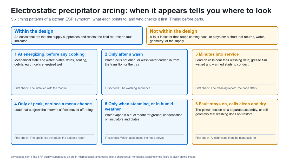
| Question | Short answer |
|---|---|
| Is any arcing normal? | An occasional arc that the supply suppresses and resets is within the design of a two-stage kitchen unit; a fault indicator that keeps coming back is not |
| Why does it arc right after installation? | Mechanical state and water: plates out of parallel, a wire broken or slack, something left inside, a cell not seated, cells energized wet, wash water carried in from the transition |
| Why does the power pack trip ten minutes into cooking? | Load: grease aerosol and vapor reach cells that are near their washing date, the film conducts, the supply protects itself; look at the cleaning record and the upstream filters before the power section |
| Why does it smell of burnt oil after months? | Clean outlet plus smell: the UV-C or carbon stage is spent. Hazy outlet plus smell: loaded plates or grease standing in the tray |
| Why is there still smoke at the outlet? | Smoke at the roof terminal with the field on points to airflow above rating or to cells due for a wash; smoke spilling at the hood front is a separate capture question that no in-duct unit treats |
| What do I record? | The 6-Pattern ESP Fault Log: symptom, first appearance, what the line was doing, panel reading, last wash, upstream state |
- What electrostatic precipitator arcing is, and when it is within the design
- What the published manuals say: the numbers a two-stage unit runs on
- Six patterns: when the symptom appears tells you where to look
- Why the power pack trips ten minutes after cooking starts
- Arcing after installation: mechanical and water causes first
- A burnt-oil smell after months: which stage is talking
- Smoke at the outlet with the unit energized
- What the code asks of the unit around these symptoms
- The 6-Pattern ESP Fault Log
- Three worked readings of the log
- Who does what, what to ask the manufacturer in writing, and where this guide stops
- Buyer record and key takeaways
- Frequently asked questions
What electrostatic precipitator arcing is, and when it is within the design
An arc is the field giving way. The ionizing wires sit at high voltage, the collector plates sit at ground, and the air gap between them is the insulation. The US EPA’s training course on precipitators, written for the industrial units at power stations and cement kilns, puts it in one sentence: raising the applied voltage increases the field strength and ion formation until sparkover occurs, and sparkover is a sudden rush of localized electric current through the gas layer between the two electrodes, which causes an immediate short-term collapse of the electric field. That text is hosted in the ESP Lesson 1 of a knowledge base that reproduces the course.
The same course says something about industrial units that does not carry over to a kitchen cabinet, and the difference matters for what counts as normal. Large single-stage industrial precipitators are run on purpose at voltages high enough to cause some sparking, because the gain in field strength outweighs the losses, and the course gives an average sparkover rate of 50 to 100 sparks per minute for optimum operation of those units. A two-stage kitchen unit is a different machine: a separate ionizing zone and a separate collecting zone, closely spaced washable plates, and a switched-mode supply whose job is to hold the field steady as the grease load builds rather than to ride the edge of sparkover. The 50 to 100 figure describes a power-station collector; it is not a target for the unit in your duct, and this page does not give one.
On our in-duct units the SPP supply suppresses an arc in microseconds and resets itself after a short circuit, which means an occasional arc is normal and a fault indicator that keeps coming back is not. That sentence from our cleaning guide is the whole boundary. Where the model carries the smart HMI panel it shows real-time voltage, current and field status with power, work and fault indicators, and the LK-E series cabinets add work, clean and fault indicator ports plus a BMS port, so the same reading can be carried to a building management system. What the panel reads at the moment of the symptom is line 4 of the log, and it is the line that tells the two apart.
The published manuals of other two-stage units draw the same line, and they draw it on the indicator light. The Smog-Hog SGN owner’s manual tells the operator to watch the power-pack light daily and gives four states: a solid light is normal operation; an occasional flash is intermittent arcing, a normal condition that will need servicing at some point; a continuous flash means the product requires servicing, with internal arcing or a dead short; no light means a faulty indicator or a product that is not operating, to be serviced immediately. Trion’s KES kitchen manual reads the same light by sound: a flickering light with an arcing noise is a high-resistance short, and a light that is not glowing is a dead short or an open circuit. The same manual expects arcing on a first start, from construction dust in the cells, and says it should subside quickly; if it is continuous, recheck the cell for trash, damaged plates or cracked insulators. Greenheck’s Grease Trapper manual uses a green light for a powered cell; while the ionizer section arcs the green light goes off and a red one comes on, while the collector section arcs both stay off, and the manual says the arcing should subside after a short period. Those are work lights read on their own units; the fault indicator on ours is a different signal, and the point of quoting them is the shared boundary, not the color code.
| What you observe | What it is | What the published manuals call it | What to do with it |
|---|---|---|---|
| A snap now and then; the panel shows the field back on; no fault indicator | An arc the supply suppressed and reset, within the design | Smog-Hog: occasional flashing, normal; Trion: arcing that subsides quickly on start-up | Note the time and the cooking in the log; no call |
| Snapping that repeats through a service; the fault indicator comes on, clears, comes on again | A short that keeps returning: a cell near its washing date, water, or a mechanical fault | Smog-Hog: continuous flashing, product requires servicing; Trion: flickering light with arcing noise, a high-resistance short | Fill the log and read the pattern below; those manuals treat it as a service condition, and the pattern and the cleaning record decide where that service starts |
| Fault indicator stays on; the field does not return | A persistent short, or the power section itself | Trion: an indicating light that is not glowing, a dead short or an open circuit; Smog-Hog: a power-pack light not illuminated, service immediately. Their lights go dark where our fault indicator comes on; the condition is the same | Isolate as the manual directs; a service call, with the log |
| A smell with the field on and the outlet clean | Not an electrical symptom; the odor stages | Not an indicator-light condition in any manual read for this page | Read the smell section; the cells are not the first suspect |
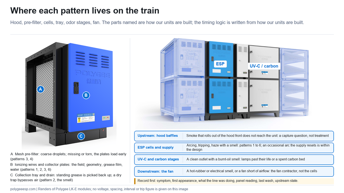
One disclosure before the patterns: this page is written by a manufacturer of in-duct precipitators, and the parts named, the SPP supply, the drawer-format cells, the mesh pre-filter and the airflow distribution plate, are how our kitchen electrostatic precipitator units are built. Other makes split the ionizing and collecting functions differently, and the panel and the interlocks vary. The timing logic is written from how our two-stage units are built; on another make, read it against that maker’s manual. The names of the parts are ours.
What the published manuals say: the numbers a two-stage unit runs on
A two-stage kitchen unit runs inside a band of voltage, velocity, temperature and humidity, and each maker prints its own band in its manual, datasheet or design guide even where ours is not printed on this site. The figures below are theirs, read from the documents linked in the references, and they are quoted for one reason: each is a figure that its own document says a selection or a symptom is checked against, and together they show the kind of number to ask for. They are not one universal range. Our own units carry their own figures, stated per model in the quotation and the manual, and this page does not substitute another maker’s number for ours.
Across the documents read for this page, ionizer voltages are printed between 10 and 13 kVDC and collector voltages between 5 and 7.5 kVDC; cell velocities run from a nominal 250 fpm (about 1.3 m/s) for heavy duty on one maker’s table to recommended maxima of 1.85 to 2.5 m/s on others; inlet temperature maxima are 56 to 60 °C, with one design guide placing a performance caution above 55 °C; and one datasheet caps relative humidity at 75%. Each document also says what it expects beyond its own figure: arcing above the voltage band, lost efficiency above the velocity, a short where condensation forms.
| Parameter | Published figure | Source | What it bounds |
|---|---|---|---|
| Ionizer voltage | 12.5 to 13.0 kVDC (Trion KES); 10.0 to 11.8 kVDC operating range; a reading above 12.0 kVDC has two causes in the manual, ionizer wires heavily coated with contaminant or a run-away power pack, and the pack is tested with its high-voltage leads disconnected before it is replaced (Smog-Hog SHN); 10,000 V DC on the ionizing wires (Captive-Aire) | Trion KES IOM p. 7; Smog-Hog SHN manual p. 16; Captive-Aire ESP manual p. 15 | The field that charges the particles; too high and the gap breaks down, too low and the manual treats the reading as a fault |
| Collector voltage | 6.0 to 6.5 kVDC (Trion KES); 5.0 to 7.5 kVDC, with continuous cell arcing above 7.5 kVDC and power pack replacement above 7.6 kVDC (Smog-Hog SHN); 5,000 V DC on every other plate (Captive-Aire) | Same documents | The field that holds the charged particles; the voltage the plate spacing is designed for |
| Cell velocity | 250 fpm (about 1.3 m/s) for heavy and extra-heavy-duty cooking, 500 fpm (about 2.5 m/s) for light and medium duty (Captive-Aire); single-pass maximum 1.85 m/s and double-pass maximum 2.5 m/s, above which efficiency is likely to fall below 95% at 0.3 micron (Camfil); maximum recommended 2.5 m/s (Airclean); works between 2 and 3 m/s, with efficiency compromised significantly at 4 to 5 m/s (AOS) | Captive-Aire manual p. 7; Camfil design checklist; Airclean product page; AOS manual | Pattern 4 and the smoke section: a fan rebalanced upward can take the cells past the maker’s recommended velocity |
| Inlet temperature | Maximum operating temperature 60 °C (Airclean); exhaust below 60 °C, with the instruction to cool the flue gas down as the remedy for a hot inlet in its troubleshooting table (a Chinese maker’s kitchen ESP manual); working range 4 to 56 °C (Purified Air ESP 1500E datasheet); above 55 °C the performance of particulate filtration may drop below required levels (Camfil) | Airclean page; kitchen ESP manual pp. 5, 10, 29; Purified Air datasheet; Camfil checklist | Solid fuel, charbroilers and short duct runs; the question our solid fuel guide sends to the quotation |
| Humidity and condensation | Maximum relative humidity 75% (Purified Air datasheet); condensation that occurs in ductwork “will short circuit ionizing-collecting cells” (Greenheck Grease Trapper), and Trion’s manual says the same of condensation in its own words | Purified Air datasheet; Greenheck IOM p. 7; Trion KES p. 4 | Pattern 5: steam on the duct and a cold cabinet at the start of a service |
| Wet cells | “Startup of a wet system will cause dead short conditions to the ionizer and collector cell circuits”; wet cells go to a warm room to dry, and hand-wiping insulators and blowing cells dry with compressed air shorten the drying time (Smog-Hog SGN) | Smog-Hog SGN manual p. 19 | Pattern 2: the drying step between washing and energizing |
| Detergent residue | Residue left by an incomplete rinse “may contribute to voltage bleed-down” (Smog-Hog); alkaline residue on the insulators “would cause creepage”, so insulators are rinsed with clean water and wiped dry (kitchen ESP manual) | Smog-Hog SGN p. 19; kitchen ESP manual p. 25 | Pattern 2 again, from the wash chemistry rather than the water |
| Cleaning methods that bend plates | Trion’s manual tells the operator not to use high-pressure steam cleaning equipment on the cells, because it can deform the plates and cause excessive arcing; close-up and prolonged blasts of high pressure or temperature from a pressure washer cause cell plate deformity requiring a replacement set (Smog-Hog SGN) | Trion KES p. 8; Smog-Hog SGN p. 19 | Pattern 6 arriving by way of the washing method |
| Washing frequency | For medium to high particulate loads, manual cell clean every 5 to 14 days and automatic wash every 3 to 7 days, given as rough values from industry experience that depend on cuisine, hours and hood filters (Camfil); daily manual washing “is not unusual” on heavy units (Trion); a daily wash cycle on self-washing units (Captive-Aire, Greenheck) | Camfil checklist; Trion KES p. 7; Captive-Aire p. 18; Greenheck p. 12 | Patterns 3 and 4; the same direction as our 15 to 30 days for a general lunch-and-dinner restaurant and 7 days for a heavy line, meaning wok frying, deep frying or charcoal |
Three things in that table change how a symptom is read. First, on the units whose manuals are quoted here the ionizer and the collector are two circuits at two voltages, and those manuals read the two separately, which is why a reading of one circuit does not condemn the other; which readings our own panel gives, and per section or per unit, is stated in the manual for the model. Second, the run-away figures in the Smog-Hog manual, above 12.0 kVDC on the ionizer and 7.6 kVDC on the collector, are a reminder that a power pack can fail high as well as low, and that manual’s first troubleshooting step is to check the power pack with its high-voltage leads disconnected, so that a pack fault and a cell fault are told apart by measurement rather than by symptom. Third, the velocity and temperature figures are selection figures, and a unit that was selected inside its maker’s figures can be moved past them later by a rebalanced fan, a demand-control system or a change of appliance; that is pattern 4, and no amount of washing moves it back.
The Smog-Hog manual adds one more relationship worth having in hand: contaminant build-up decreases the high voltage to the ionizer and collector circuits, and a heavy coating on the ionizer wires is one of two causes it gives for ionizer voltage rising above its band. The same stack of grease that makes a cell arc also shifts the voltages the panel shows, which is why line 4 of the log is a reading, not a yes or no.
Six patterns: when the symptom appears tells you where to look
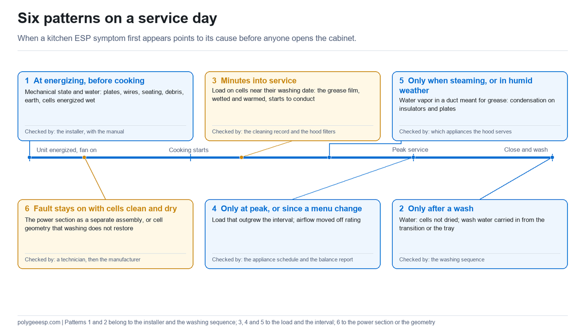
The time a symptom first appears sorts its causes into six groups, and each group is checked by a different person with a different document. Reading the pattern first is what stops a load problem from being treated as a parts problem, and a mechanical fault from being washed again and again.
The six patterns below are the frame for every section that follows, and the first column is what to write down before anything else.
| Pattern: when it first appears | Points to | Why the timing fits | First check, by whom | Which section |
|---|---|---|---|---|
| 1. At energizing, before any cooking, on a new unit or one whose cells were just refitted | Mechanical state and water | On a new unit no grease has arrived yet, and on a refitted one the cells were just handled; what the field finds first is what the installation left: geometry, debris, moisture | Cells drawn and looked over against the installation drawing; the installer, with the manual | Installation |
| 2. Only after a wash | Water | Cells energized before they dried, or wash water carried into the cabinet from the transition or the tray | The washing sequence and the drying step; the kitchen team or the contractor who washes | Installation; Code |
| 3. Minutes into service, with the fan already running | Load on cells near their washing date | Grease aerosol and vapor arrive with the cooking; a film that is already there starts to conduct as it is wetted and warmed | The cleaning record against the stated interval; the upstream filters; the kitchen manager | Ten minutes |
| 4. Only at peak, or only since a menu or hours change | Load that outgrew the interval; airflow moved off rating | The cell loads faster than the schedule written for the old duty; a rebalanced fan changes what reaches the cells | The appliance schedule and hours against the interval; the balance report; the contractor | Ten minutes; Smoke |
| 5. Only when the line is steaming or boiling, or in humid weather | Water vapor in a duct meant for grease | Condensation on insulators and plates gives the field a path that dries out later | Which appliances the hood serves; whether a dishwasher or steamer is on the same duct; the engineer | Ten minutes |
| 6. Fault indicator stays on with cells clean, dry and seated | The power section, or cell geometry | Nothing on the plates explains it; what is left is the supply or a bowed stack, a broken wire, a cracked insulator | The power section as a separate assembly; a technician, then the manufacturer | Who does what |
Two patterns can overlap on one unit. A cell with a slightly bowed plate may hold its field when clean and lose it as grease narrows the gap further, which reads as pattern 3 until a wash fails to clear it, when it becomes pattern 6. The log is what shows the change: a unit that cleared after every wash and now does not has moved out of the interval question, and the geometry and the power section are what the technician looks at next; the repair-or-replace questions apply from that point.
Why the power pack trips ten minutes after cooking starts
A unit that holds its field with the fan running and loses it once cooking is under way is pointing first at the load, and the power section is read after the load has been ruled out. Three things happen as a line comes up to speed, and together they are one account of the delay before the trip; the log is what tests it.
First, the cooking sends grease aerosol and water vapor down the duct, and the hood’s baffle filters and the unit’s mesh pre-filter take the coarse fraction, so what reaches the ionizing wires and the plates is the fine fraction the unit exists to collect. Second, that fraction lands on whatever is already there. A cell within its interval presents mostly plate surface; a cell near or past its washing date presents a grease film, and a film wetted by vapor and warmed by the exhaust conducts in a way it did not at seven in the morning, with the fan on and the burners off. Third, the supply does what it is built to do: it suppresses each arc and resets, and a fault indicator that keeps coming back is the sign that the short it reset is still there. Read from the kitchen floor, that is a power pack that trips ten minutes after the chef starts; read from the cabinet, it is a cell that may be asking for its wash.
The first document to open is the cleaning record, read against the interval stated for the model and the menu, and the second is the hood and the pre-filter. We state the interval for a given model and duty in writing with the quotation. As a working range for a general lunch-and-dinner restaurant the cells are washed every 15 to 30 days, and on a heavy line, meaning wok frying, deep frying or charcoal grilling, every 7 days; the four things that move the interval, the cooking, the hours, what is upstream and the airflow, are set out on the cleaning page. A baffle filter left out after a hood clean, or a torn mesh pre-filter, sends the coarse droplets it should have caught straight onto the plates, and a cell that was on schedule can reach the state its wash date was meant to prevent well before that date. It is a finding to look for whenever a unit is said to be underperforming, and it is found by looking at the hood, not the cabinet.
Water has its own version of the ten-minute trip. A dishwasher, a steamer or a boiling line puts water vapor into the exhaust, and when that vapor reaches a cabinet that is still cool at the start of a service it condenses on the insulators and the plates before the duct has warmed. Steam from a dishwasher or a steamer is water, is served by a Type 2 hood, and is a different problem from cooking fumes; which hood serves which appliance is set out in type 1 hood vs type 2. A unit on a duct that also takes a steam appliance can show pattern 5 on the days that appliance runs, and the log entry that names the appliance is what separates it from pattern 3.
When the power section is the suspect
The power section becomes the suspect when the cells are clean, dry and seated and the fault indicator still stays on, which is pattern 6, or when the trip arrives after the same interval regardless of what is cooking. On our units the high-voltage supply is a separate assembly from the cell pack, and it carries its own UL file, E514664, separate from the file covering the units themselves (E522667), so a dead power section does not condemn the cells and a damaged cell does not condemn the supply. The SPP modules have passed third-party full-load trials at minus 40 and 80 degrees Celsius; what the ambient is at the position where the cabinet sits, in a plant room without ventilation or on a roof in the Gulf, is a line for the log, because a plant room at the top of its range is a different question from a cell at the end of its interval. On other makes the split between supply and cells may or may not exist, and the question to put to the original supplier is whether the power module is orderable on its own.
Arcing after installation: mechanical and water causes first
A unit that arcs from the first energizing, before cooking, has the cooking load off the list for that moment: on a new unit nothing has been collected, and on a refitted one the cells were just handled. What the field finds is what the installation left, and the causes fall into two groups: the mechanical state of the cells and the cabinet, and water.
The mechanical group is the geometry that creates the field. A collection cell is a stack of closely spaced plates and an ionizing section, and plate spacing is what the field depends on. Plates bowed out of parallel in transit, in unboxing or when a cell was slid home on its rails; an ionizing wire broken, slack or displaced in handling; a cell not seated to the end of its rails; a fastener, a wire offcut, a strip of packing or a piece of duct swarf left inside the cabinet; a chassis earth not connected. Bent plates, a displaced wire and debris can give the high-voltage side a path to ground; a cell not seated or an earth not connected is an installation fault the technician reads at the panel. None of them is changed by washing. Our replacement guide puts the limit plainly: recovery stops being possible when the geometry has gone, meaning plates bowed out of parallel, ionizer wires broken or missing, insulators cracked or tracked, and at that point the cell is a parts purchase at minimum. On a new installation the first question is whether the geometry was intact when the crate was opened, which is why the pre-shipment inspection and the unboxing record exist.
The water group is simpler, and it belongs to the first start, before any load has arrived. Cells are washed off the machine and go back on their rails; a cell energized before it has dried carries water between plates that were made to hold an air gap. A pre-start wash of a new duct, a wet-cleaned cabinet, or a transition duct that lets wash water run toward the unit instead of toward its drain pan all put water where the field is. The washing sequence on the cleaning page ends with the cells returned to service, and the drying between washing and energizing is a step of its own, taken as the manual for the model directs.
Trion’s initial start-up list for its KES units covers the same ground in a maker’s own words. Its first four items, of eight: inspect the adjoining ductwork and cabinet to be sure they are clean and free of debris or construction materials, with the drain basin openings free of restrictions and the duct sealed liquid-tight at the cabinet collars; inspect the ionizer and collecting cells to see that all ionizing wires are intact, no large pieces of foreign material are lodged between the plates, the high-voltage insulators are not cracked, and the cells are properly installed; check that the primary wiring is on the proper terminals; be sure the drain lines are completely connected and properly terminated, with a trap or seal to prevent air bypass. The Smog-Hog manuals add the states that fail the field, in their weekly inspection and their post-cleaning checks: ionizer wires taut and centered between straight, parallel ground plates; no contaminant bridging between the cell plates or at the support corners; standoff and feed-through insulators clean and white after cleaning, with cracked or carbon-tracked insulators replaced.
The order of checking on a first-start arc is geometry, debris, seating and earth, then water, then the transition and the drain, and the supply after those. The ecology unit installation page covers the transition sections, the access on the cell side and the drain arrangement that a position needs; the code clause on transition slope is in the code section below. A first-start arc on a unit whose cells are straight, dry and seated, in a cabinet that is clean and earthed, is the case where the supply moves to the front of the list.
A burnt-oil smell after months: which stage is talking
A smell is read with the outlet. The particulate stage and the odor stages fail in different ways, and whether the discharge is visibly clean at the moment of the smell is the first thing that separates them.
Clean outlet, burnt-oil or rancid smell: read the odor stages first. A kitchen ecology unit puts a UV-C module and an activated carbon module behind the precipitator, and both are consumed, by different clocks. The UV-C lamps run on a clock whether the kitchen is busy or not, and a lamp past its life may still glow while its output has fallen, so the lamp hours, not the light, are the record. The carbon bed is consumed by gas-phase load, so the menu and the hours set its pace, and a spent bed looks like a fresh one; our carbon filter guide covers how exhaustion is read. A carbon bed that has taken grease because an upstream stage was missed is a bed that holds what it was not placed there to hold. Which of the three stages is washed and which are bought is set out in ecology unit filters; how long each consumed stage lasts is stated for the site, not in general, and a smell with a clean outlet is one of the signs that a consumed stage is due.
Hazy outlet, same smell: read the precipitator side first. Collected grease is still grease, and a film across loaded plates sits in a warm exhaust stream through every service. So does grease standing in the collection tray, which is grease available to be picked back up by the airstream; draining and wiping the tray is part of every cell wash for that reason. A unit that smells and shows haze at the terminal is a unit whose cells and tray are past their date, and six months without a wash is well beyond the 15 to 30 days written for a general lunch-and-dinner restaurant and the 7 days for a heavy line, meaning wok frying, deep frying or charcoal. The grease is also a fire question, because grease in a duct is the fuel of a kitchen duct fire, and the duct downstream of a loaded unit is collecting what the unit no longer holds.
One smell belongs to neither group. A sharp, clean, chlorine-like smell near the discharge of a unit with a UV-C stage is a question about ozone, not oil, and it has its own limits and evidence on our electrostatic precipitator ozone page.
| Outlet at the moment of the smell | Smell | Stage speaking | What to record | What follows |
|---|---|---|---|---|
| Visibly clean | Burnt or rancid oil | UV-C lamps past their life, or a spent carbon bed | Lamp hours or installation date; carbon installation date; menu and hours since | Consumables on their own clocks, not a cell wash; see ecology unit filters |
| Haze or grease at the terminal | Burnt or rancid oil | Loaded plates; grease standing in the tray | Last wash date; who washed; whether the tray was drained | The cleaning regime, and the duct downstream |
| Either | Sharp, chlorine-like | A UV-C stage: ozone | Where it is smelled and when the lamps run | The ozone page; a workplace limit question |
| Either | A hot-rubber or electrical smell | The fan, its belt and its motor, and the electrical parts of the unit, read before the cells | What the fan sounds like; its amp draw if read; what the panel shows | The fan contractor or the technician; isolate if it is strong |
Smoke at the outlet with the unit energized
Three different things look like a failed precipitator from the street, and they are told apart before the unit is blamed. Our guide on how to reduce smoke from commercial kitchen exhaust works through the three places smoke escapes; here is the version for a unit that is already installed and energized.
Smoke that rolls out of the hood front does not reach the unit. It is a capture question, exhaust rate, make-up air, appliance position against the overhang, and no treatment stage in the duct fixes what the hood did not collect. Smoke that passes the unit with clean cells and a steady field, at a visible level at the terminal, points to airflow: a unit run above its rated airflow does not collect the way it was tested to, because the tested efficiency, up to 97.6% grease removal on our LK units in CMA-accredited third-party tests, was measured at rated, evenly distributed airflow, which is the condition the airflow distribution plate exists to produce. Our DW/172 guide reads clause 24.6 of that BESA specification as a warning on the same point: care in selection, because at higher velocities small particles can pass through untreated. A fan rebalanced upward since the unit was selected, or a demand-control system moving the flow, is pattern 4. Smoke that returns between washes, from cells that collected well when clean, points to the interval first.
The record that settles which of the three you have is the same six-line log, with one addition: a photograph of the terminal at peak, taken from the same vantage point on a day the cells were freshly washed and on the day of the complaint. A difference between the two photographs points to the interval; no difference sends the question to capture, to airflow, or to the treatment stage itself, as the replacement guide sets out.
What the code asks of the unit around these symptoms
Where the 2024 International Mechanical Code (IMC) applies, section 506.5.2 lists sixteen items for the installation of pollution-control units, and four of them sit directly behind the symptoms on this page. None of them diagnoses a unit, but each one changes what the installation should already have, and a symptom on an installation that lacks one of them has one more candidate cause to record before the cabinet is opened.
| IMC 2024, section 506.5.2 | What it asks | Which symptom it sits behind | Who answers it |
|---|---|---|---|
| Item 9 | An airflow differential pressure control monitoring the pressure drop across the filter sections, with a visual alarm in the cooking area when airflow falls below the design velocity | Pattern 4: a loaded unit raising its resistance until the fan is short of airflow; the alarm is the installation’s own signal that airflow has fallen | The mechanical engineer and the controls contractor; the alarm is part of the installation, not something this page claims every unit carries |
| Item 12 | Wash-down drains discharging through a grease interceptor, the drains sized for the flow and sealed with a trap or other approved means against air bypass and, where a trap is used, with a seal depth that accounts for the system pressurization and evaporation between cleanings | Pattern 2 and the smell: a seal that has failed lets air bypass through the drain, and a drain that does not run leaves grease standing in the tray | The plumbing contractor, to the drawing |
| Item 14 | Grease duct connections in accordance with section 506.3.2.3; where water splash or carryover can occur in the transition duct from a washing operation, the transition slopes downward toward the cabinet drain pan for not less than 18 inches (457 mm); ducts transition to the full size of the unit’s inlet and outlet | Pattern 2: wash water that runs toward the cells instead of the pan; a transition that chokes the inlet puts uneven flow on the cells | The duct contractor, to the installation drawing |
| Item 16 | Pollution-control units maintained in accordance with the manufacturer’s instructions | Patterns 3 and 4, and the smell: the interval and the sequence are the manufacturer’s, and a regime that departs from them is a departure from this item | The operator; the manufacturer’s instructions for the model, with the written interval from the quotation as one of them |
One more item frames the unit itself. Item 1 asks for the unit to be listed and labeled to UL 8782; our LK and SE 6K, 12K and 18K models are UL 867 Listed under File E522667, and we hold no listing to UL 8782, as our weight and roof support guide also states. The edition adopted where you operate may be earlier than 2024 and may number these items differently; read the adopted text before relying on an item number. Outside the United States the clauses are different, and this page has not read another country’s mechanical code for them.
The 6-Pattern ESP Fault Log
The 6-Pattern ESP Fault Log is our own working sheet, not a code form or a manufacturer’s service record. It is six lines, kept from the first symptom, and its purpose is to let the pattern be read by whoever arrives next, the kitchen manager, the contractor or us, without a second visit to find out what was happening when the fault indicator first came on. Copy it, fill in what you know, and send it with any service request or parts enquiry.
| # | Line | What to write | Which pattern it separates | Who reads it |
|---|---|---|---|---|
| 1 | The symptom | Snapping heard; fault indicator on, clearing or staying; field lost on the panel; smell, and what kind; smoke, and where seen | Electrical from odor from capture | Everyone |
| 2 | When it first appeared | At energizing before cooking; only after a wash; minutes into service and how many; only at peak; only when steaming or in humid weather; since a menu or hours change; with cells clean and dry | All six | The technician, before the visit |
| 3 | What the line was doing | Appliances running and their fuel; whether a dishwasher or steamer was on; whether a wash had just been done | 3 from 5; 2 from 1 | The kitchen manager |
| 4 | The panel reading | Voltage, current and field status where the model shows them; which indicator was lit; whether a BMS alarm was logged | Within the design from a returning short | The technician and the manufacturer |
| 5 | The last wash | Date, who did it, whether the tray was drained and the pre-filter refitted, the stated interval for the model and menu | 3 and 4 from 6 | The operator and the contractor |
| 6 | The upstream state | Hood baffles in place; mesh pre-filter in place and intact; any fan rebalancing or demand-control change since selection | 4 from 3; capture from treatment | The contractor and the engineer |
Three worked readings of the log
Teaching examples only. The three sites below are constructed to show how the six lines are read; they are not service records, and the readings are the pattern each log points to, not a diagnosis of any real unit.
A grill house that trips ten minutes into dinner
Line 1: fault indicator comes on about ten minutes after the first orders, clears when the line slows, returns at the next rush. Line 2: started three weeks ago; no change in hours. Line 3: charcoal grill and two fryers; no steam appliance on the duct. Line 4: panel current rises and the field drops out at the trip. Line 5: last cell wash 26 days ago, by the kitchen team; tray drained; the written interval for the model and this menu is 7 days. Line 6: hood baffles in place; mesh pre-filter found torn at the last wash and not replaced. Reading: pattern 3 with line 6 shortening it; a charcoal line at 26 days against a 7-day interval, with the pre-filter gone, is the pattern of a cell presenting a film by the first rush, and the cells are what the technician draws and looks at first. The first actions are a wash and a new pre-filter; the power section is read after them, or at once if the panel reading says so.
A new installation that arcs at the first switch-on
Line 1: continuous snapping from the moment the field is energized, fan running, kitchen not yet open. Line 2: first energizing. Line 3: nothing cooking; the duct was pressure-washed by the installer two days ago. Line 4: fault indicator on continuously. Line 5: cells never washed; they went in from the crate. Line 6: hood filters fitted; transition duct installed level, not sloped to the drain pan. Reading: pattern 1 or 2, and the log narrows them: a level transition after a duct wash can put water where the field is, and cells slid in from a crate are not recorded as checked for a bowed plate or a displaced wire. The installer draws the cells, dries and inspects them against the maker’s full start-up list, corrects the transition slope that item 14 of IMC section 506.5.2 asks for where wash water can reach the unit, and energizes again. The supply is checked as the manual’s own troubleshooting step directs; in the Smog-Hog manual that is the first step, with the leads disconnected, and it runs alongside the geometry and water checks rather than after them.
A hotel unit that smells of burnt oil after six months
Line 1: burnt-oil smell at the roof discharge, reported by the floor above; no snapping, no fault indicator. Line 2: began about a month ago, worse through each service. Line 3: all-day buffet, mostly frying and roasting. Line 4: panel normal. Line 5: cells washed every two weeks by a contractor; the UV-C lamps and the carbon module have not been touched since commissioning six months ago. Line 6: hood baffles in place; the discharge photographed at peak is visibly clean. Reading: the smell section’s first row, a clean outlet with a burnt-oil smell, so the odor stages are read first: the lamps are on a clock with no record of hours, and the carbon has taken six months of all-day load with no change date. The cells are not the first suspect, because the fortnightly wash and the clean discharge give no reason to put them first; the service request goes to the consumables, with the lamp hours and the carbon date asked for, and the cells are looked at if the smell survives the change of lamps and carbon.
Who does what, what to ask the manufacturer in writing, and where this guide stops
The symptoms on this page are read by three people, and the boundary between them is the cabinet door. The kitchen team observes and records, and on our in-duct units draws and washes the cells where the manual for the model allows it, with the unit switched off and isolated before the door is opened; opening the maintenance door on those units breaks the high-voltage circuit through magnetic switches, and that interlock is a backstop, not a replacement for the isolation step in the manual. The technician looks over the ionizing wires and the insulators while the cells are out, replaces a broken wire, reads the panel and the power section, and decides between a cell that washes clean and a cell whose geometry has gone. The manufacturer states the interval for the model and the menu, supplies the cell or the power module as separate parts, and answers in writing what a model carries.
| Who | Does | Does not |
|---|---|---|
| Kitchen team | Keeps the log; checks the hood baffles and the mesh pre-filter are in place; draws, washes, dries and refits the cells where the manual for the model allows; drains and wipes the tray | Open the power section; straighten a plate; replace a wire; work on the duct, the fan or the transition |
| Technician or contractor | Reads the log and the panel; inspects wires, insulators and plate geometry; replaces a wire; separates a cell fault from a supply fault; checks the drain, the trap and the transition slope | Decide the interval for a menu it has not seen; sign for what a model is listed for |
| Manufacturer | States the interval in writing with the quotation; supplies cells and the SPP module as parts; states what each model carries; reads the log with the technician | Diagnose from a description without the log; give a cleaning interval in the abstract |
Seven things to ask any manufacturer for in writing
The table of published figures above exists because those makers printed their numbers. For the unit in your duct, ours or anyone else’s, the same numbers are asked for by model, and the answers are what turn a pattern into a diagnosis. We answer each of these for our own units in the quotation and the manual for the model.
- The ionizer and collector voltage bands for the model, and what reading on the panel or at the test point means a power section outside its band.
- What the fault indicator does: whether it flashes on each reset, whether it latches after repeated shorts, and what clears it.
- The drying requirement after a cell wash, and whether the manual accepts compressed air or a warm room, and in what state the insulators go back.
- The maximum inlet temperature and humidity for the model, against the appliance line and fuel the hood serves.
- The cell velocity band the model was tested at, and the airflow at which the quoted efficiency was measured.
- The written cleaning interval for the model and the menu, and the four things that move it.
- Whether the power section is orderable on its own, and what a cell with bowed plates, a broken wire or a tracked insulator costs as a part.
What this guide does not do. It gives no service procedure beyond the order in which records are read, and no voltage, current, spacing, drying-time or trip figure for our own units; the figures quoted on this page are other makers’ published ones, cited to show the bands a two-stage unit runs in, and ours are stated per model in the quotation and the manual. It does not state an inlet temperature limit, which is a question for the quotation against a named appliance line. It does not cover the hood, the duct or the fan beyond the lines of the log that name them. It makes no first-party claim about how often any pattern occurs: this page sorts causes by timing, and the sorting is reasoning from how a two-stage unit is built and from what other makers print in their manuals, not a count of service calls. Warranty on our units runs twelve months on the complete unit and covers the collection cells and the SPP power module; UV lamps and activated carbon media are consumables and are not covered; labor and site attendance are quoted separately.
Buyer record and key takeaways
Before a service visit is booked or a part is ordered for a unit that arcs, trips, smells or shows smoke, these items are in your file.
- The 6-Pattern ESP Fault Log, filled in from the first symptom, with the pattern number you read from it.
- The cleaning record for the unit, and the written interval for the model and the menu from the quotation.
- The appliance schedule with fuel, and whether any steam appliance shares the duct.
- The latest balance report, and any fan or demand-control change since the unit was selected.
- For a first-start symptom, the unboxing or pre-shipment record and the installation drawing with the transition and the drain.
- The panel reading or the BMS log at the time of the symptom.
Key takeaways
- Timing before parts: when the symptom first appears sorts its causes into six groups, each checked by a different person with a different document.
- An occasional arc is within the design: the supply suppresses it and resets; a fault indicator that keeps coming back is the boundary, and the Smog-Hog and Trion manuals draw the same line on their indicator lights.
- The figures are published, maker by maker: ionizers between 10 and 13 kVDC and collectors between 5 and 7.5 kVDC in the manuals read here, cell velocities from a nominal 1.3 m/s for heavy duty to recommended maxima of 1.85 to 2.5 m/s, inlet maxima of 56 to 60 °C, one datasheet’s 75% humidity cap; ask for the same figures by model for the unit in your duct.
- Ten minutes in points first at load: cells near their washing date, upstream filters missing, or steam on a cooking duct, before the power section.
- First-start arcing means geometry or water: plates, wires, seating, debris, earth, then drying and the transition slope.
- Read a smell with the outlet: clean outlet, the odor stages; hazy outlet, the plates and the tray.
- The code already asks for four things where it applies: a pressure-drop alarm, a sealed drain, a transition sloped to the pan where wash water can reach it, and maintenance to the manufacturer’s instructions.
Frequently asked questions
- Why does a kitchen electrostatic precipitator keep arcing after installation?
- Arcing that starts with the first energizing, before any cooking, points to the mechanical state of the cells and to water, not to the cooking load. Plates bowed out of parallel in transit or when a cell was slid home, an ionizing wire broken or slack, a fastener or packing left inside the cabinet, a cell not seated on its rails, cells energized before they dried after a pre-start wash, and wash water carried into the cabinet by a transition duct that does not slope to the drain pan all give the field a short path to ground. Isolate the unit as the manual directs, have the cells drawn and looked over, and confirm the transition and drain against the installation drawing before any part is ordered.
- Why does my ESP trip its high-voltage power pack about ten minutes after cooking starts?
- A unit that holds its field with the fan running and loses it once cooking is under way is pointing first at the load that cooking sends it: grease aerosol and water vapor arrive at the cells and the insulators as the line warms up, and a cell that is already close to its washing date has a grease film ready to conduct. The supply suppresses the arcs and resets, and a fault indicator that keeps coming back is the sign that the short is still there. Look first at the cleaning record against the stated interval for the model and the menu, at whether the hood baffles and the mesh pre-filter are in place, and at whether steam from a dishwasher or steamer is reaching a duct meant for cooking fumes, before the power section is suspected.
- Our ecology unit smells of burnt oil after six months. What is wrong?
- Read the outlet with the smell. If the discharge is visibly clean and the smell is there, the particulate stage is the less likely source and the odor stages are read first: UV-C lamps that run on a clock and are past their life, or an activated carbon bed that is spent, which looks the same as a fresh one. If the discharge carries haze or grease along with the smell, the precipitator side is read first: a grease film across loaded plates, or grease standing in the collection tray, which the airstream picks back up. Six months without a cell wash is well beyond the working range we write: 15 to 30 days for a general lunch-and-dinner restaurant, and 7 days for a heavy line, meaning wok frying, deep frying or charcoal, with the figure for a given model and menu stated in writing with the quotation.
- We installed an ESP but you can still see smoke coming out of the exhaust. Why?
- Three different things look like a failed precipitator from the street. Smoke that rolls out of the hood front does not reach the unit, so it is a capture question at the hood and no treatment stage fixes it. Smoke that passes an energized unit with clean cells at a visible level points to airflow: a unit run above its rated airflow does not collect the way it was tested to, and our DW/172 guide reads clause 24.6 of that specification as a warning that at higher velocities small particles can pass through untreated. Smoke that returns between washes, from cells that collected well when clean, points to the interval. Settle which of the three you have from the symptom record before a second unit is discussed.
A unit that arcs, trips or smells, and a log to send?
Send us the six lines of the log, the model on the nameplate and the menu the hood serves. You get back a reading of the pattern against how the unit is built, the written interval for that model and that menu if you do not already hold it, and, where the pattern points to a part, a quotation for the cell or the SPP power module as a separate item. The visit, the isolation and anything inside the cabinet stay with your technician and the manual for the model.
Send the log and the nameplate →
If the unit is not ours, the same six lines are what we would ask for, and a fair starting point for any manufacturer’s service request; the replacement guide covers what to ask for in writing when the original supplier cannot be reached, and the kitchen electrostatic precipitator page sets out the parts named on this page.
Why we write this. The lists of causes for an arcing or tripping precipitator are long and largely agreed, and they are read in the wrong order when the first question is which part to buy. This page puts the timing of the symptom first, because the timing is what the kitchen already knows, and it sends the reader to the cleaning record, the hood and the drawing before it sends them to a parts list. It gives no service procedure, and no figure of our own that is not on our record.
Law manages project delivery at Polygee and prepares the factory documents that go into contractors’ submittals. Polygee, founded in 2004, manufactures the in-duct electrostatic precipitators, kitchen ESP hoods and kitchen ecology units named here. The code and course text cited on this page was read in the sources listed below; the parts, interlocks, interval range and warranty terms are those of Polygee’s own units as published on its product and maintenance pages, and no figure is given where the record holds none.
References & further reading
- US EPA Air Pollution Training Institute, Electrostatic Precipitator Operation course, Lesson 1 (reproduced by Neundorfer, Inc.): sparkover and the sparking rate of industrial precipitators. neundorfer.com
- International Code Council, International Mechanical Code 2024, chapter 5 Exhaust Systems: section 506.5.2, items 1, 9, 12, 14 and 16. codes.iccsafe.org
- UL Standards & Engagement, UL 867, Standard for Electrostatic Air Cleaners: scope. shopulstandards.com
- Trion, KES Series Installation, Operation & Maintenance Manual (hosted by Johnson Controls): pp. 4, 7, 8, 9 (voltages, start-up list and start-up arcing, steam cleaning, indicator lights). docs.johnsoncontrols.com
- United Air Specialists (Smog-Hog, now a Parker brand), Smog-Hog Electrostatic Precipitator Owner’s Manual, SHN series, 2015 edition: pp. 13, 15, 16 (dry-out time and post-cleaning checks, indicator light conditions, high-voltage specifications and run-away voltages). universalairsys.com
- Parker Hannifin, Smog-Hog Electrostatic Precipitator Owner’s Manual, SGN series: pp. 17, 18, 19, 20 (indicator light states, weekly inspection, dry-out time, detergent residue, plate deformity, post-cleaning insulator checks). beecleanspecialties.com
- Captive-Aire Systems, Technical Manual for Installation, Operation and Maintenance of the Electrostatic Precipitator: pp. 7, 15, 18 (cell velocity by duty, plate and wire voltages, daily wash). captiveaire.com
- Greenheck, Grease Trapper ESP Installation, Operation and Maintenance Manual, Rev. 3, July 2019: pp. 7, 11, 12 (condensation, indicator lights, wash cycle). content.greenheck.com
- Camfil, Design Checklist for Commercial Kitchen Exhaust Filtration Systems: system velocity, temperature, cleaning frequency. camfil.com
- Airclean Ltd, Electrostatic Precipitator product page: maximum face velocity and operating temperature. airclean.co.uk
- Purified Air Ltd, ESP 1500E datasheet (as filed with a UK planning application): working temperature and humidity. planning.welhat.gov.uk
- Botonair, Commercial Kitchen Electrostatic Precipitator Manual: pp. 5, 10, 25, 29 (exhaust temperature, insulator cleaning, troubleshooting). botonair.com
- AOS Australia, ESP manual, Face Velocity of ESP Units. aosaus.com.au
Related reading
- Electrostatic precipitator cleaning: what a service visit covers, what moves the interval, and how the cells are washed.
- Commercial kitchen ESP replacement: the four questions that settle repair, rebuild or replace once the pattern points to geometry or the supply.
- How to reduce smoke from commercial kitchen exhaust: the three places smoke escapes and the six fixes in order.
- Ecology unit filters: which stage is washed, which are consumed, and on what clock.