

Grease duct requirements are the part of a commercial kitchen exhaust design the fire code is unusually specific about, because the duct is where a fire has fuel. In the U.S. the rules are short and specific: 16-gauge steel or 18-gauge stainless, joints made with a continuous liquid-tight weld or braze, a slope of at least 1/4 inch per foot toward the hood or a grease reservoir, cleanouts wherever the run cannot be reached, 18 inches to combustibles, and a rated enclosure or listed wrap where the duct passes through the building.
But the duct is also where every other decision on the exhaust path shows up as a consequence. A longer route to a compliant rooftop outlet means more enclosure. A filtration unit in the run means another access point, another grease drain and, in current U.S. editions, another listing to produce. The duct is not one requirement; it is where the requirements meet.
This guide takes the grease duct rules in the order a drawing gets reviewed, from material and joints to slope, access, clearance and enclosure, then covers what changes when in-duct filtration is placed on the run.
One disclosure: Polygee builds the in-duct filtration that sits on a grease duct run. We do not fabricate or install grease duct, and nothing here is a compliance determination; the authority having jurisdiction (AHJ) applies the edition it has adopted.
Grease duct requirements, section by section
Every grease duct rule exists for one of two reasons: to keep liquefied grease moving to somewhere it can be collected, or to keep a duct fire from reaching the building. The International Mechanical Code (Section 506.3, Ducts Serving Type I Hoods) sets the construction rules; NFPA 96 sets matching rules and adds the operating side.
| Item | What the code asks for | Where it is decided |
|---|---|---|
| Material | Steel at least 0.0575 in (1.463 mm), 16 gauge, or stainless steel at least 0.0450 in (1.14 mm), 18 gauge | IMC 506.3.1; NFPA 96 |
| Joints, seams, penetrations | Continuous liquid-tight weld or braze on the external surface; internal welds allowed only if ground smooth with ready access for inspection | IMC 506.3.2; NFPA 96 |
| Slope | At least 1/4 in 12 (2%) toward the hood or a grease reservoir; at least 1 in 12 (8.3%) where a horizontal run exceeds 75 ft (22.9 m) | IMC 506.3; NFPA 96 |
| Cleanouts | Where the duct cannot be reached from the hood or the outlet: openings not more than 20 ft (6.1 m) apart and not more than 10 ft (3 m) from a change of direction greater than 45 degrees; doors of duct-thickness steel, installed liquid-tight | IMC 506.3.8 |
| Clearance | At least 18 in (457 mm) to combustible construction where an enclosure is not required | IMC 506.3.6 |
| Enclosure | A fire-resistance-rated shaft, or a listed and labeled field-applied enclosure system evaluated to ASTM E2336, where the duct passes through the building | IMC 506.3.11 |
| Dedicated run | Serves Type 1 hoods only; not combined with any other exhaust system. Whether several hoods may share one duct is decided by the engineer and the AHJ | IMC 506.3 |
| Testing | Leak-tested before concealment | IMC 506.3.2.5 |
Three of these deserve a closer look.
The weld. Grease duct is not sheet-metal duct. The joint has to be a continuous, liquid-tight weld or braze, made on the outside, so that grease cannot seep into a seam and a fire cannot find a gap. On field-built duct, bolted flanges, sealant, tape and snap-lock seams are what get a duct rejected; listed factory-built grease duct joins per its own listing. Where the fabricator wants to weld from the inside, the code allows it only if the joint is ground smooth and can be inspected.
The grease duct slope. A quarter inch per foot is a small number that is easy to lose across a long run with hangers set to the ceiling rather than to the duct. The consequence is a low point where grease pools, which is both a fire load and a leak. Runs over 75 feet steepen to an inch per foot, which is why very long horizontal runs are avoided in design rather than sloped after the fact.
The duty of the duct. Everything in the table applies because the duct serves a Type 1 hood, and it applies to the whole run to the outlet. Which cooklines put a hood in that category is the subject of type 1 hood vs type 2.
What is the difference between Type 1 and Type 2 grease ducts?
There is no such thing as a Type 2 grease duct. A grease duct is, by definition, the duct serving a Type 1 hood, and every rule on this page applies to it. A Type 2 hood serves heat- and steam-only equipment; its duct follows the ordinary duct sections of the code, not the grease duct sections. If a specification talks about a “Type 2 grease duct,” it usually means a Type 2 hood duct, and the requirements are different enough that the wording is worth correcting before it reaches the fabricator.
Grease duct cleanout requirements: where the IMC and NFPA 96 differ
The two documents agree on why access matters and disagree on the spacing. Both want every part of the run reachable for inspection and cleaning; they measure it differently.
The IMC rule is written around inaccessibility: any section that cannot be reached from the hood or the discharge opening gets cleanout openings no more than 20 feet apart and no more than 10 feet from any change of direction greater than 45 degrees. The doors are steel of at least the duct’s thickness and are installed liquid-tight.
NFPA 96 is written around the person doing the cleaning: on horizontal ducts, at least one opening of 20 by 20 inches (508 by 508 mm) for personnel entry, and where an opening that size is not possible, openings large enough for thorough cleaning at intervals of 12 feet (3.7 m). Access panels are of the same material and thickness as the duct, greasetight, with a gasket or sealant rated for 1,500°F (816°C).
On a real project the tighter of the two governs wherever both are adopted, and the panels tend to end up where the cleaning contractor needs them anyway: at every turn, at the fan inlet, and on both sides of anything mounted in the run. UK projects arrive at the same panels from the other direction, because the access has to let a contractor measure a mean grease deposit along the system, which is the test in the TR19 Grease cleaning standard. That last case is where filtration equipment enters, covered below.
Clearance, enclosure and grease duct fire wrap
Clearance and enclosure answer different situations. Where the duct runs in open space and no enclosure is required, it keeps at least 18 inches from combustible construction and 3 inches from noncombustible construction and gypsum board; those distances sit alongside the hood’s own in commercial kitchen hood clearance requirements. Where that clearance cannot be kept in a tight ceiling, whether a listed enclosure system installed to its listing is the route is a question for the AHJ before the duct is drawn. The same section rules out fire dampers and smoke dampers in a grease duct, and what carries the separation in their place is set out in fire dampers in a commercial kitchen extract. Where it passes through other parts of the building, floors, ceilings, concealed spaces, the code requires it to be protected, by one of two routes.
The first is a fire-resistance-rated shaft: the duct runs inside a rated enclosure built as part of the building. The second is a listed and labeled field-applied grease duct enclosure system, the wrap, evaluated for that purpose under ASTM E2336. The wrap is a common answer in retrofits because it follows the duct without rebuilding the ceiling. The rating required depends on the building, and the adopted edition sets it; the point for planning is that every foot of concealed run carries the enclosure with it, which is why a re-route to a compliant outlet costs more than the duct alone.
Two things the wrap is not. It is not insulation in the thermal sense, even though it insulates; ordinary duct insulation does not satisfy the enclosure requirement. And it does not change the cleanout rule: access openings through a wrapped duct need the wrap’s own listed access detail, which is one more reason to fix the cleanout positions before the wrap goes on. The leak test the code requires before concealment belongs in the same slot: it is done on the bare duct before the wrap or enclosure covers the joints, and it is worth asking the AHJ whether they want to witness it.
In-duct filtration on a grease duct: what the run has to provide
A filtration unit placed in the grease duct becomes part of the grease duct for code purposes, and the run has to be designed around it. An electrostatic precipitator is one such unit, so this is the section that concerns us directly, and it is worth being precise about what the code asks and what it does not.
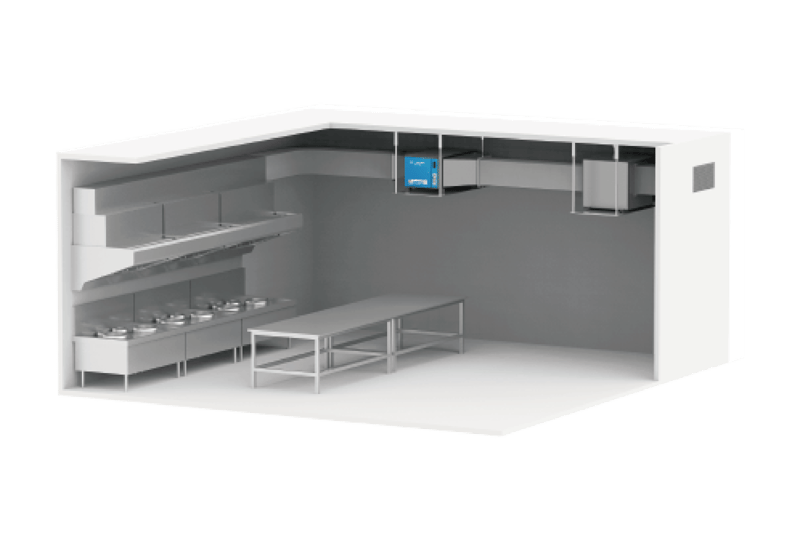
The IMC and NFPA 96 both treat the unit as a pollution control unit (PCU), the category an electrostatic precipitator falls into. Four requirements follow from that, and all four belong on the drawings:
- Listing. The 2021 IMC requires pollution control units to be listed and labeled to UL 8782, the UL outline written for units installed in line with commercial grease ducts; the 2018 edition referenced UL 1978. Which edition asks for which document, and what the listing does and does not prove, is set out in what a pollution control unit is. Fans serving a PCU have to be listed to UL 762. Where the unit sits inside an enclosed duct system, it has to be listed for that enclosure under UL 2221 or ASTM E2336. Which listings the reviewer will ask for depends on the edition adopted, so this is the first question to put to the supplier and the AHJ together. In practice this also decides where the unit can go: if the only space for it is inside the enclosed part of the run, ask the supplier whether the model carries an enclosure listing; if it does not, plan the unit where the run is not required to be enclosed, with its access on both sides.
- Access on both sides. The collector cells of an electrostatic precipitator come out for washing, which puts the unit in the same position as a cleanout: it needs clear withdrawal space and a service door, and the duct on either side of it needs its own access so the run stays cleanable. Ask the supplier for the cell withdrawal clearance for the model.
- Grease drainage. An electrostatic precipitator collects grease by design, so it needs a drain to a container that is noncombustible, closed, rainproof and structurally sound (NFPA 96), the same kind of container the rest of the run drains to, and it sits on the sloped section rather than at a low point where grease would pool against it.
- Fire protection. NFPA 96 treats the unit as part of the hood-duct-suppression system, and both NFPA 96 and the Uniform Mechanical Code (UMC) require the ductwork downstream of a PCU to carry an approved automatic fire-extinguishing system. The unit is reviewed with the suppression design, not added after it; the rest of that design is in commercial kitchen hood fire suppression requirements.
What the code does not do is size the ESP. That comes from the hood exhaust rate, set out in commercial kitchen hood CFM requirements, and from the resistance the unit adds to the run: a complete Polygee in-duct kitchen electrostatic precipitator, airflow-distribution plate included, is rated at ≤150 Pa; ask for the figure at your design airflow, and carry that in the fan static-pressure calculation next to the duct itself, as set out in commercial kitchen exhaust fan requirements. Grease removal efficiency is measured at rated, evenly distributed airflow, so ask the supplier what inlet arrangement the model needs, how much straight duct ahead of it and whether the distribution plate covers a short inlet, and draw that into the run rather than fitting it afterward.
Once the kitchen is running, the duct and anything in it fall under the inspection and cleaning schedule in commercial kitchen exhaust cleaning requirements, and the outlet the duct ends at follows the distances in commercial kitchen exhaust termination requirements. The full plan-review chain around the hood is in commercial kitchen hood code requirements.
Where this guide stops
Eight boundaries on these grease duct requirements, so the table is used for what it is:
- Edition and amendments. The figures are the IMC and NFPA 96 model text. Jurisdictions adopt different editions and amend them, and the PCU listing reference in particular changed between editions. Confirm the adopted edition before a number or a listing goes on a drawing.
- Outside IMC and NFPA 96 jurisdictions. Singapore, the Gulf, Southeast Asia and Europe set their own grease duct rules. The logic transfers; the gauges, slopes and spacings do not.
- Enclosure ratings. The hours of fire resistance required for a shaft or wrap depend on the building; that figure comes from the adopted code and the wrap listing, not from this page.
- Factory-built grease duct. Listed prefabricated grease duct systems follow their own listing for construction, joints and clearance. This page describes field-built duct.
- Not a design. Duct sizing, velocity, static pressure, hanger design and the suppression layout are the mechanical and fire-protection engineers’ work, and the AHJ signs off on the result. How the velocity floor turns into a ceiling on duct area, and what that section then decides about in-duct equipment, is worked through in commercial kitchen exhaust duct size.
- Solid-fuel cooking. Wood and charcoal cooking runs on a separate exhaust system with rules of its own, set out in solid fuel cooking exhaust requirements.
- UMC jurisdictions. Where the Uniform Mechanical Code is adopted in place of the IMC, the grease duct provisions have their own section numbers and text; this page quotes the IMC.
- Vertical risers. The access figures here are for horizontal ducts; for a vertical riser read the riser provisions from the adopted edition.
Frequently Asked Questions
- What are the grease duct code requirements?
- Under the International Mechanical Code, a duct serving a Type 1 hood is a grease duct: steel of at least 16 gauge or stainless steel of at least 18 gauge, with joints, seams and penetrations made by a continuous liquid-tight external weld or braze, sloped at least 1/4 inch per foot toward the hood or a grease reservoir (1 inch per foot where a horizontal run exceeds 75 feet), fitted with cleanouts where it cannot be reached from the hood or outlet, kept 18 inches from combustibles where no enclosure is required, and enclosed by a rated shaft or a listed wrap where it passes through the building. NFPA 96 sets matching material, joint and slope rules with its own access-opening spacing. The adopted edition and any local amendment are what your authority having jurisdiction enforces.
- What is the minimum slope required for a grease duct?
- The IMC requires grease duct systems to slope at least 1/4 unit vertical in 12 units horizontal, a 2 percent grade, toward the hood or toward a grease reservoir. Where a horizontal grease duct is longer than 75 feet, the slope rises to at least 1 unit vertical in 12, an 8.3 percent grade. NFPA 96 sets matching figures: 2 percent on horizontal runs up to 75 feet and 8 percent beyond. The point of the slope is that liquefied grease drains back to somewhere it can be collected rather than pooling in the run. The adopted edition and any local amendment govern which figure applies.
- Does a grease duct need to be fire wrapped?
- Where a grease duct passes through other parts of the building, the code requires it to be protected: either inside a fire-resistance-rated shaft or with a listed and labeled field-applied enclosure system, a wrap evaluated for grease duct service under ASTM E2336. Which route, and what rating, depends on the building and the adopted edition. Where an enclosure is not required, the duct instead keeps a clearance of at least 18 inches to combustible construction. Wrap and clearance answer different situations; where the clearance cannot be kept, ask the AHJ whether a listed enclosure system is the route.
- Does a grease duct have to be insulated?
- Not for thermal reasons. The code does not ask for insulation on a grease duct; it asks for fire protection where the duct passes through the building, which is met by a rated shaft or a listed enclosure wrap, and for clearance to combustibles elsewhere. A listed wrap system happens to insulate the duct as a side effect, which is why the two get confused. If a specification calls for insulation, ask whether it means a listed grease duct enclosure system, because ordinary duct insulation does not satisfy the enclosure requirement. Confirm the wording with the adopted edition and your AHJ.
Placing a filtration unit on a grease duct run?
Send us the duct route with the hood exhaust rate, where the unit can sit, and which code edition the project is reviewed under, and our project team will come back with the model that fits the airflow, its resistance at that airflow for the fan calculation, the access and drain details the run has to provide, and the third-party test reports for the model we propose, together with a plain statement of which listings that model carries and which it does not, so you can check them against the edition your reviewer applies.
Talk to our project team →Law manages kitchen exhaust filtration projects at Polygee, from spec review through duct-side ESP sizing and installation support. Polygee, founded in 2004, builds commercial kitchen exhaust filtration equipment. This article summarizes published model-code requirements for planning purposes only — it is not a compliance determination, so confirm every figure and listing for a specific installation with your engineer, your local AHJ and the adopted edition of the code.
References & further reading
- International Mechanical Code (IMC), Chapter 5: Exhaust Systems — Section 506.3, Ducts Serving Type I Hoods, and the pollution control unit provisions. codes.iccsafe.org
- Uniform Mechanical Code (UMC) — pollution control unit provisions. iapmo.org
- NFPA 96, Standard for Ventilation Control and Fire Protection of Commercial Cooking Operations — exhaust duct systems and pollution control units. nfpa.org
- UL 8782, Pollution Control Units for Commercial Cooking Operations; UL 762, Power Roof Ventilators for Restaurant Exhaust Appliances; UL 2221, Tests of Fire Resistive Grease Duct Enclosure Assemblies. ul.com
- ASTM E2336, Standard Test Methods for Fire Resistive Grease Duct Enclosure Systems. astm.org
- Polygee — kitchen exhaust filtration product range and third-party test reports. polygeeesp.com