

A commercial kitchen hood fire suppression system, in the pre-engineered wet chemical form compared on this page, is a set of detectors, a release mechanism, a pressurized tank of wet chemical agent and fixed nozzles that discharges onto the cooking surfaces, into the hood plenum and into the exhaust duct when a detector or a pull station actuates it. A kitchen fire suppression system also shuts off fuel or power to the appliances, and the listing of the installed brand fixes its design.
This guide follows the duct as far as the exhaust goes, because that is where our equipment sits: an in-duct electrostatic precipitator, or a three-stage kitchen ecology unit with UV-C and activated carbon behind it, added to a run that the hood system already protects. The codes treat that equipment as a pollution control unit with fire protection of its own, the suppression manufacturers’ listed designs do not all reach it, and the controls have to agree on what the fan and the precipitator do in a fire. Those questions are cheaper to settle on the drawing than at the final inspection.
This page helps you decide what to ask the suppression contractor and the equipment supplier before either is ordered: how the system acts, in what order and with which numbers; how often it is serviced and where the documents disagree; and what an ESP or ecology unit in the run adds. It ends with The 12-Line Suppression Interface Sheet, a record to attach to the request for quotation. It gives no installation, reset or recharge procedure: those belong to a licensed fire suppression contractor working to the manual of the listed system. The order in which a plan reviewer reads the code is on our hood fire suppression requirements page.
| Question | Short answer |
|---|---|
| What does it protect? | Three zones in the listed design: the cooking appliances, the hood plenum and filters, and the exhaust duct |
| How is it triggered? | Automatically, by fusible links on a cable, a pneumatic detection tube or electronic detectors, or by hand at a pull station 10 to 20 ft from the kitchen exhaust system, at or near the way out (IFC 2015, 904.12.1) |
| What does it discharge? | A potassium-based wet chemical that cools the grease and forms a soap-like layer on it; systems are tested to UL 300 |
| What else happens at discharge? | Fuel or electric power to the cooking equipment is shut off and is reset by hand; make-up air inside the hood stops; the exhaust fan question differs by document |
| How often is it serviced? | At least every six months and after any discharge; fusible links every six months or every year depending on the document adopted; tank hydrostatic test every 12 years in the manuals read |
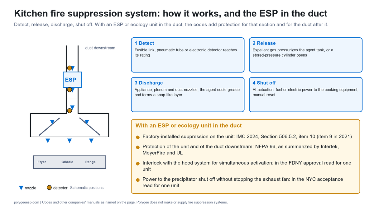
| What changes with an ESP in the duct? | The 2024 IMC asks a pollution control unit for a factory-installed suppression system; NFPA 96, as summarized by Intertek, MeyerFire and UL, asks for protection of the unit and of the duct downstream; at least one suppression manufacturer refers pollution control units to its technical services outside its listed design |
| What do I take away? | The 12-Line Suppression Interface Sheet: who supplies each piece, where it is written, and what breaks if it is missing |
- What a kitchen fire suppression system is, and the three zones it covers
- How it works: detection, release, discharge and shutoff
- The numbers in three published manuals
- Why wet chemical, and what UL 300 changed
- What changes when an ESP or ecology unit is in the duct
- Fan on or fan off: where the documents differ
- Who installs it, who services it, and how often
- After a discharge: the hood, the duct and the precipitator
- The 12-Line Suppression Interface Sheet
- Frequently asked questions
What a kitchen fire suppression system is, and the three zones it covers
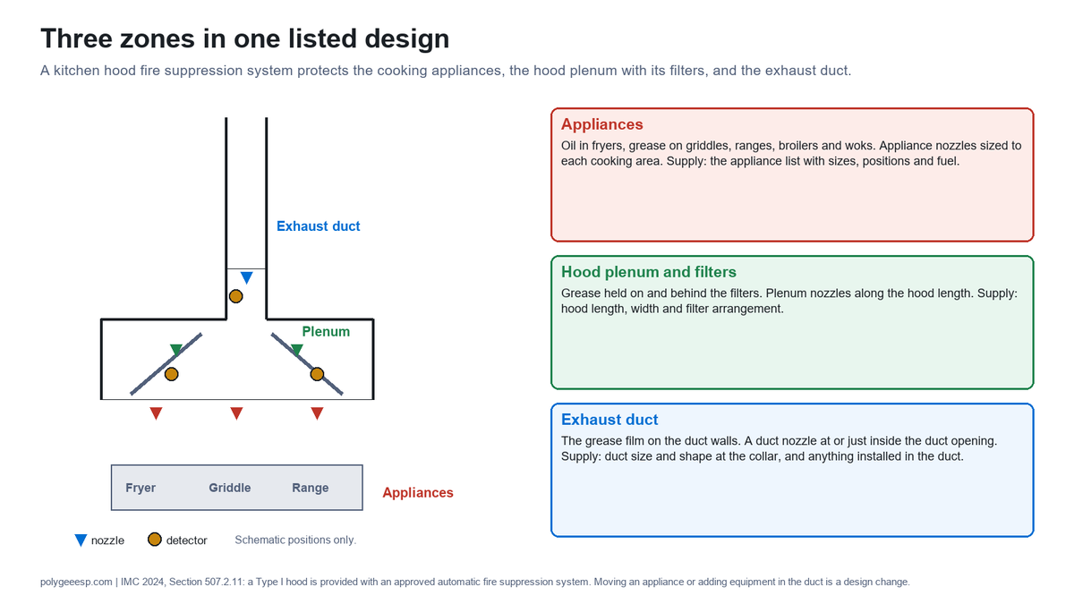
A kitchen hood fire suppression system is a pre-engineered extinguishing system whose nozzle positions, pipe lengths and agent quantities are set by its listing, and which protects three zones: the cooking surfaces, the hood plenum with its filters, and the exhaust duct. The International Mechanical Code makes it part of every Type I hood: in the 2024 IMC, Section 507.2.11, a Type I hood “shall be provided with an approved automatic fire suppression system” complying with Section 904.13 of the International Building Code and the International Fire Code; the 2021 edition carried the same rule in Section 509.1.
The three zones are protected for different reasons. The appliance nozzles put agent on burning oil in a fryer, on a griddle or on a broiler, where the fire data place the start of most restaurant fires: in the US Fire Administration’s analysis of 2002 data, cooking caused about 64% of an estimated 7,100 restaurant structure fires, grease and cooking oil were the material first ignited in 68% of the cooking fires, and deep fryers were involved in 31% of them. The plenum nozzles protect the space behind the filters, which collects grease that the filters stop. The duct nozzle protects the start of a run that is lined with grease between cleanings and, once alight, carries fire away from the kitchen.
| Zone | What burns there | How it is protected | What the buyer supplies for the design |
|---|---|---|---|
| Cooking appliances | Oil in fryers, grease on griddles, ranges, broilers and woks | Appliance nozzles sized to each appliance’s cooking area and height | The appliance list with sizes, positions and fuel; any later change goes back to the contractor |
| Hood plenum and filters | Grease held on and behind the filters | Plenum nozzles along the hood length | Hood length, width and the filter arrangement, from the hood drawing |
| Exhaust duct | The grease film on the duct walls | A duct nozzle at or just inside the duct opening, listed for an unlimited duct length in the Ansul and Amerex manuals | Duct size and shape at the collar, and anything installed in the duct |
Two things follow for anyone who later changes the line. The design belongs to one listed system, so moving a fryer, adding a broiler or inserting a treatment unit in the duct is a design change for the suppression contractor, not a matter of moving a nozzle. And the system is one part of the fire protection: the grease duct construction, the clearances and the cleaning interval carry the rest.
How it works: detection, release, discharge and shutoff
A kitchen fire suppression system works through four actions started by one actuation: a detector reaches its rating, the release mechanism pressurizes the agent tank or opens a cylinder already under pressure, the agent is pushed through the piping to the nozzles, and switches tied to the actuation shut off the fuel or power to the cooking equipment. The shutoff belongs to the actuation; it does not wait for the discharge to finish. A pull station starts the same actuation by hand.
- Detection. On a mechanical system, fusible links sit in detector brackets in the hood and the duct opening, held on a steel cable under tension; a link that reaches its temperature rating separates and the cable lets go. The Ansul R-102 manual allows up to 15 detectors on one detection run, 14 in series and one terminal detector. Other systems use a pneumatic tube along the hood instead of links: Amerex’s Zone Defense datasheet describes a linear detection tube listed by UL for 435 °F, pressurized to 70 psi. Electric detection is a third route on some systems.
- Release. The release mechanism, mechanical or electric, works in one of two ways in the manuals read. In the Ansul R-102 it opens a cartridge of nitrogen or carbon dioxide that pressurizes the agent tank, with a regulator controlling that pressure. In the Amerex KP and Pyro-Chem Kitchen Knight II, the agent cylinder is already stored under nitrogen pressure and the release opens its valve.
- Discharge. The agent flows through the distribution piping to the appliance, plenum and duct nozzles at a predetermined rate. On a burning grease surface it cools the grease and reacts with it, a process the Ansul manual calls saponification, forming a layer of soap-like foam that insulates the hot grease from the air and holds back combustible vapor.
- Shutoff and signals. Under the 2015 International Fire Code, Section 904.12.2, the actuation of the system “shall automatically shut down the fuel or electrical power supply to the cooking equipment.” The reset is manual. The Ansul manual adds that make-up or supply air fans internal to the protected hood shall shut down; alarms, a building fire alarm connection and other interlocks are tied in where the design calls for them.
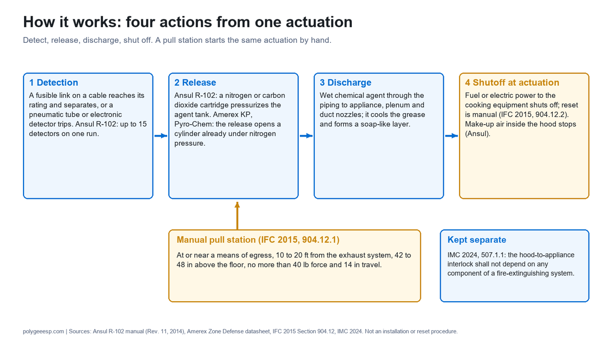
The manual route is there because a fire can be seen before a link melts. The 2015 IFC, Section 904.12.1, puts the manual actuation device at or near a means of egress from the cooking area, a minimum of 10 ft and a maximum of 20 ft from the kitchen exhaust system, 42 to 48 in above the floor, needing no more than 40 lb of force and no more than 14 in of movement. The same code, in Section 904.12.5, asks for portable extinguishers within 30 ft of travel of the cooking equipment, of the Class K type where oils and fats are cooked.
One rule in the mechanical code keeps the two systems apart: the 2024 IMC, Section 507.1.1, says the interlock between an exhaust hood system and the cooking appliances “shall not involve or depend on any component of a fire-extinguishing system.” The interlock that keeps the appliances off while the Type I exhaust fan is off is therefore designed without relying on any part of the suppression system.
The numbers in three published manuals
The design numbers of a kitchen fire suppression system come from the manual of the listed brand, and the manuals read for this page agree on the method but not on every figure. The table puts the Ansul R-102 (Tyco, Rev. 11, 2014), Amerex KP (manual P/N 12385) and Pyro-Chem Kitchen Knight II (Part No. 551274-06, 2014) figures side by side, with the International Fire Code where it sets a number of its own. These are their figures, not ours: Polygee does not make suppression systems.
| Item | Ansul R-102 | Amerex KP | Pyro-Chem Kitchen Knight II | What it decides for the buyer |
|---|---|---|---|---|
| Agent and charge | Potassium-based ANSULEX Low pH, in 1.5 gal and 3.0 gal charges | Cylinders of 3.75 gal (up to 11 flow points) and 6.14 gal (up to 18), nitrogen-pressurized to 240 psi at 70 °F | Cylinders PCL-160, -300, -460, -600; the model number is the capacity (PCL-300 holds 3.0 gal); nitrogen at 225 psig at 70 °F | How many tanks the hood line needs, and where they hang |
| Tank hydrostatic test | Every 12 years under normal conditions | Every 12 years (DOT 4BW240 cylinders) | 12-year maintenance includes the hydrostatic test | A service cost every 12 years, on the record |
| Fusible link ratings | 165, 212, 280, 360, 450 °F, and 500 °F in one style; a 360 °F link is for ambient up to 290 °F | Globe Type K fusible links 212, 280, 360, 450 °F; quick-response glass-bulb Job Links 286, 360, 450, 500 °F; a 360 °F quick-response link is for ambient up to 300 °F | Links of 165, 212, 280, 360, 450 and 500 °F; ambient limits not summarized here | The rating at each position is read from that brand’s maximum-ambient table, so a hot broiler line takes a higher rating |
| Detectors on one run | Up to 15: 14 series and 1 terminal | Its own detection-line limits; not summarized here | Its own fusible link line limits; not summarized here | Long cooklines may need more than one detection run |
| Duct nozzle coverage | One 1W nozzle: up to 50 in perimeter or 16 in diameter; one 2W nozzle: up to 100 in or 32 in; a 1W and a 2W together: up to 135 in perimeter, rectangular only | One nozzle: up to 50 in perimeter or 16 in diameter, unlimited duct length; the diagonal of the duct may not exceed 18.8 in without more duct nozzles | One IL nozzle: up to 50 in perimeter with a longest side of 16 3/4 in and a diagonal of 18 3/4 in, or 16 in round; one 2D nozzle: up to 100 in perimeter, with a diagonal of 37 3/8 in; square or rectangular ducts above 100 in modularized, with no round duct option | A large duct collar takes more nozzles and more agent; perimeter alone does not settle it |
| Duct nozzle position | 2 to 8 in into the duct | 2 to 8 in into the duct opening, centered | 0 to 6 in into the opening, on the centerline, for a general duct; the manual sets other positions for a listed damper and for a transition taller than 4 ft | The duct collar needs room for the nozzle and a detector |
| Plenum | One 1W nozzle per 4 linear ft of plenum, end nozzles within 2 ft of the hood ends, plenum no wider than 4 ft | Its own plenum nozzle limits; not summarized here | Its own plenum nozzle limits; not summarized here | Nozzle count rises with hood length; a wide plenum needs the manual’s own case |
| Manual pull station (IFC 2015, 904.12.1) | 10 to 20 ft from the exhaust system, at or near a means of egress, 42 to 48 in above the floor, no more than 40 lb force and 14 in travel | Its position goes on the kitchen layout before walls are finished | ||
| Portable extinguisher (IFC 2015, 904.12.5) | Within 30 ft of travel; Class K for oils and fats; one Class K unit of at least 1.5 gal for up to four fryers of no more than 80 lb of oil each, with a separate rule for a larger single fryer | Counted from the fryer schedule | ||
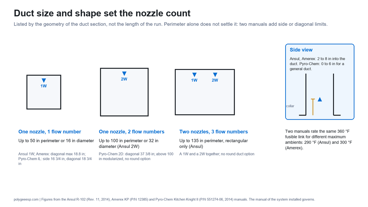
Two differences in that table are worth reading twice. The same 360 °F link is shown for a maximum ambient of 290 °F by one manual and 300 °F by another, so a link schedule copied from one brand’s manual is not valid for another. And the duct nozzle is listed by the geometry of the duct section, its perimeter or diameter and, in two of the manuals, its side or diagonal, not by the length of the run, which is why the duct size and shape at the collar are what the contractor asks for.
Why wet chemical, and what UL 300 changed
Kitchen hood systems use wet chemical agents because the test that lists them, UL 300, was rewritten in 1994 for hotter appliances and vegetable oils, and the dry chemical systems of the time did not pass it. Amerex’s technical note on Class K fires describes the change: the revised UL 300 of November 1994 tests on a real deep fat fryer, raised the pre-burn before extinguishment from one minute to two, added a splash test, and requires the fire to stay out without reflash for 20 minutes. The same note says no existing dry chemical system passed, and that wet chemical systems needed up to five times more agent to pass.
Two kitchen changes drove the rewrite, in the same note: energy-efficient appliances that hold their heat, and a move from animal fats to vegetable oils, which ignite at a higher temperature and are harder to keep out once they have burned. The Ansul manual lists what a UL 300 test covers: fires started in deep fat fryers, ranges, griddles, char-broilers, woks, upright and chain broilers, filters, plenum chambers, hoods and ducts after the appliance is loaded with grease, each allowed to reach full intensity before the system is actuated.
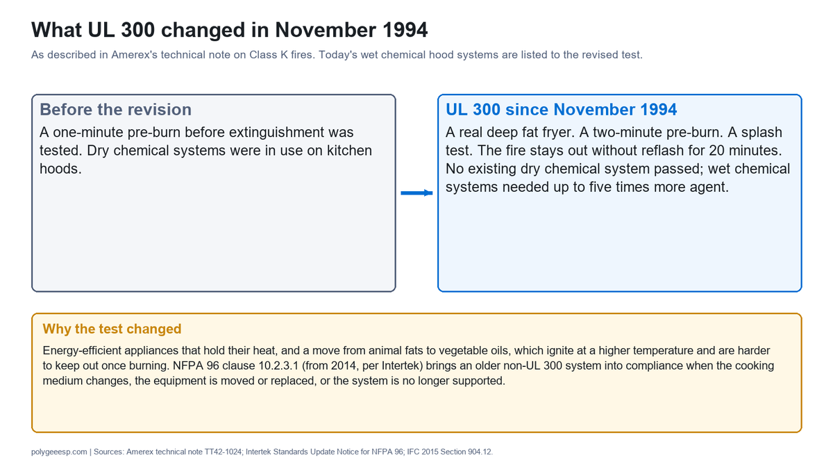
The codes then caught up with the installed base. The 2015 IFC, Section 904.12, requires pre-engineered wet and dry chemical systems for commercial cooking to be tested to UL 300. In its 2014 edition NFPA 96 revised clause 10.2.3.1, which according to Intertek’s standards update notice requires an older system that is not UL 300 compliant to be brought into compliance when the cooking medium changes from animal fats to vegetable oils, when the cooking equipment is moved or replaced, or when the system is no longer supported by its manufacturer. A renovation that changes the cooking oil, moves or replaces equipment, or finds the old system unsupported meets that clause, and the check belongs in the same review as any new duct equipment.
What changes when an ESP or ecology unit is in the duct
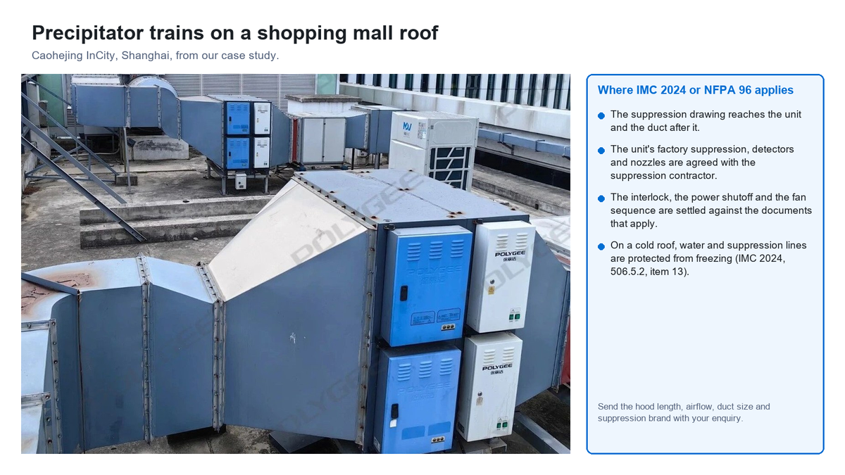
An electrostatic precipitator or a kitchen ecology unit installed in the exhaust duct is treated by the codes as a pollution control unit, and it brings two fire protection requirements with it: protection of the unit itself, which the 2024 IMC asks to be factory-installed, and protection of the duct downstream of it. Neither is covered automatically by the hood system, and at least one suppression manufacturer’s listed design stops short of a pollution control unit.
What the codes ask for
- IMC 2024, Section 506.5.2, item 10: “Pollution-control units shall be provided with a factory-installed fire suppression system.” In the 2021 edition the same requirement is item 9. Item 13 of the 2024 edition asks for protection from freezing for the water supply and fire suppression systems where they are subject to it, which applies to a rooftop unit in a cold climate.
- IMC 2024, Section 506.5.2, item 1: the unit is listed and labeled to UL 8782. UL Solutions, in a 2019 article on the history of these units, says that UL-listed pollution control units manufactured after April 30, 2020 are assessed to UL 8782 and that a pollution control unit must have fire suppression.
- NFPA 96: the 2017 edition added clause 10.1.3, quoted in Intertek’s update notice: air pollution control devices “or other devices installed in the exhaust duct, shall be protected by an automatic fire-extinguishing system”. MeyerFire quotes 2017 clauses 9.3.3 and 9.3.3.1 as requiring that protection to cover the component sections of the equipment and the ductwork downstream, and the UL article says that the UMC and NFPA 96 require the ductwork downstream of the pollution control unit to include an approved automatic fire-extinguishing system.
- NFPA 96, clause 9.3.1.3 (from the 2011 edition, per Intertek): space at every access panel for the safe removal and servicing of filters, electrostatic precipitator cells and odor control media beds.
What the suppression manuals say about precipitators
The suppression manuals read for this page treat a precipitator in the duct as a design case of its own. The Ansul R-102 manual covers an ESP at or near the base of the duct: duct nozzles above the precipitator aimed downstream, plus one half-flow 1/2N nozzle for each cell, centered 10 to 26 in below the precipitator and aimed at the center of the cell (closer only where 10 in is physically impossible), and detectors both below the precipitator at the base of the duct and in the duct just above it. The same manual then says, of pollution control units or air scrubbers with or without ESPs, to contact its technical services for a non-UL listed recommended application. The Pyro-Chem Kitchen Knight II manual says ducts with electrostatic precipitators must be protected above and below the unit with standard duct nozzles, and, where the precipitator is at or near the base of the duct, a detector below it and one just above it. The Amerex KP manual read for this page gives no precipitator design case.
What the unit manufacturers and approvals show
- Factory pre-piping, field completion. Greenheck’s Grease Trapper ESP manual states that the suppression nozzles are factory pre-piped while the tanks, controls and fusible-link detectors are installed in the field, that the release and tanks should be no more than 5 ft from the unit, and that the fire system must be installed and operational to maintain the UL listing of the unit.
- Wet chemical or water. Captive-Aire’s C-ESP manual offers a factory-mounted Ansul wet chemical system or, for units installed indoors, a pre-piped water spray connected to the building’s wet-pipe sprinkler system, with bulb-type nozzles rated at 325 °F, and a 250 °F thermostat in the filter section.
- One trigger for both systems. The New York City Fire Department’s 2025 certificate of approval for a Captive-Aire pollution control unit requires its suppression system to be interlocked with the kitchen hood suppression system for simultaneous activation, with detectors activating at 360 to 600 °F, and the protection to cover the filter sections and the duct downstream.
- Power to the precipitator. The New York City Department of Buildings acceptance for a Trion Air Boss KES precipitator requires fire protection at the inlet, at the outlet and within the precipitator, and requires the fire protection to shut down electric power to the precipitator without shutting down the exhaust fan.
- Wash cycles. On units with automatic washing, Greenheck’s controller lists “Fire Active” among the conditions that prevent a wash from starting, or stop one in progress, when a kitchen fire is detected.
- Carbon media. Captive-Aire’s manual says an all-carbon odor media option must have a fire suppression system installed to protect it because it is flammable, and warns against applying fire-retardant chemicals to the ventilator or the precipitator. A kitchen ecology unit has an activated carbon stage behind the precipitator and UV-C, so the carbon stage is a line on the suppression drawing in its own right.
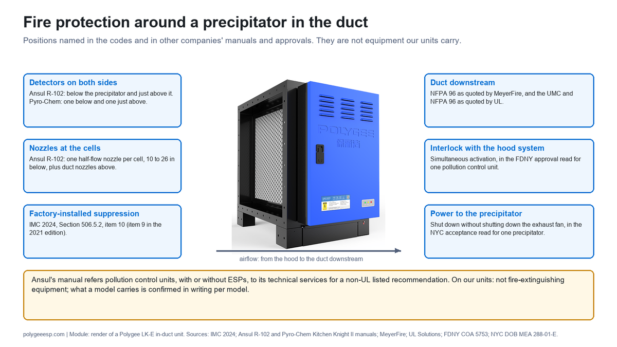
Where Polygee stands. Our in-duct units are washable stainless-steel collector cells in a duct-mounted housing; they are not fire-extinguishing equipment, and we do not supply the suppression. Three of our models, LK/SE-6K, LK/SE-12K and LK/SE-18K, are UL 867 Listed under File E522667; we hold no listing to UL 8782, and we say so. Whether a model ships with any factory-installed suppression is confirmed in writing per model with the quotation. That makes the four items below a joint task for the suppression contractor, the mechanical contractor and us, and the earlier they are on one drawing, the fewer of them are decided at the final inspection.
| Item for the drawing | What the documents above ask | Who answers it | What we provide for it |
|---|---|---|---|
| Protection of the unit | Factory-installed suppression (IMC 2024, 506.5.2 item 10); protection of each section (NFPA 96 as quoted) | The unit manufacturer, the suppression contractor and the authority having jurisdiction | A written statement per model of what it carries and does not carry; dimensions and access sides for nozzle and detector positions |
| Protection of the duct downstream | An approved automatic fire-extinguishing system downstream (NFPA 96, UMC, as quoted by UL) | The suppression contractor | The unit’s outlet size and position on the drawing |
| Interlock with the hood system | Simultaneous activation, in the FDNY approval read | The suppression contractor and the electrician | Which signals the unit’s control panel accepts or gives, stated in writing per model |
| Power to the precipitator in a fire | Shut off, without shutting down the exhaust fan, in the NYC acceptance read | The electrical designer, against the adopted code | The power supply arrangement of the model, so the shutoff can be wired to it |
The pollution control unit clauses are set out in full, as questions to put to a supplier, on our commercial kitchen ventilation system page, and the term itself is explained on our pollution control unit page.
Fan on or fan off: where the documents differ
Whether the exhaust fan runs during a discharge is answered differently by the suppression manuals and by some of the pollution control unit documents, so the answer for a given kitchen is a design decision to write on the control drawing, not a default. The suppression manuals favor a running fan; the Captive-Aire unit manual stops it on one trigger and starts it on another; the New York acceptance for the Trion unit keeps it running and stops the precipitator.
| Document | Exhaust fan at discharge | Other fans and power | Reason given |
|---|---|---|---|
| Ansul R-102 manual | Should be left on; the system is UL listed with or without fan operation | Make-up or supply fans internal to the protected hood shut down | The draft helps move the agent through the system and cools the plenum and duct afterward |
| Pyro-Chem Kitchen Knight II manual | Should remain on; UL listed with or without exhaust fan shutdown | All fuel and power to the protected appliances shut off | The fans assist dispersion of the agent through the ventilating system |
| Captive-Aire C-ESP manual, internal fire mode (its 250 °F thermostat) | Off | Supply fan off; the ventilator’s damper, where fitted, to its fire position; cells off; water spray on | A fire inside the unit |
| Captive-Aire C-ESP manual, external fire mode (the hood, duct or unit chemical system) | On at once if it was off; where the internal mode is also active, the manual gives it priority, and the external mode follows only after the internal mode and its 2-minute cool-down cycle, with the exhaust fan still off during the cool-down | Supply fan off; water spray after a 60-second delay | To remove smoke and heat, and give the chemical system time to work first |
| NYC Buildings acceptance, Trion Air Boss KES | Not shut down | Electric power to the precipitator shut down | Condition of the acceptance |
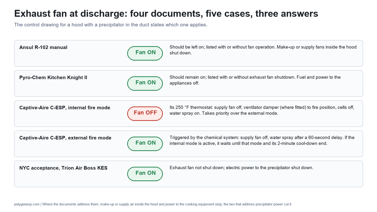
Read together, the documents leave one point to the design. Where they address the others, they agree that make-up or supply air inside the hood stops and that power to the cooking equipment stops, and the two that address precipitator power, the Captive-Aire manual and the New York acceptance, cut it. Whether the exhaust fan runs is set by the listed suppression design, the unit’s own fire mode and the adopted code, and the place to settle it is the line on The 12-Line Suppression Interface Sheet that names the fan.
Who installs it, who services it, and how often
A kitchen fire suppression system is designed and installed by a contractor authorized for the brand, serviced at least every six months and after every discharge, and its fusible links are replaced every six months or every year depending on the document that applies. The owner’s part is a monthly look, a check that the detectors are clean, with any cleaning of them left to the service company, and a record.
| Interval | What happens | Source |
|---|---|---|
| Monthly | Owner inspection of the system | NFPA 17A clause 7.2.1, as quoted in the Uintah Fire Suppression Special Service District checklist (edition not stated) |
| Every six months, and after any activation | Service by a qualified person | IFC 2015, 904.12.6.2 (six months and after activation); NFPA 96 (2011) 11.2.1 as quoted by the Minnesota Department of Health (six months); the Ansul and Pyro-Chem manuals |
| Every six months | Metal-alloy fusible links replaced | NFPA 96 (2011) 11.2.4 as quoted by the Minnesota Department of Health; the Pyro-Chem manual; Amerex recommends it |
| At least once a year | Fusible links and automatic sprinkler heads replaced, frangible bulbs excepted (IFC); fusible-alloy sensing elements replaced (NFPA 17A) | IFC 2015, 904.12.6.3; NFPA 17A clause 7.3.3 as quoted by Uintah; Amerex: never more than one year in service |
| At least once a year | Rubber nozzle blow-off caps replaced (metal caps are not on this yearly list); distribution piping blown through | Ansul R-102 manual |
| Every 12 years | Agent tank hydrostatic test | All three manuals; NFPA 17A clause 7.5.1 as quoted |
| After the hood and duct are cleaned | Inspection of the system, because cleaning chemical on the detectors can stop them working | Ansul R-102 manual, which recommends the inspection; NFPA 96 (2011) 11.6.7 as quoted by the Minnesota Department of Health: no cleaning chemical on fusible links or detectors |
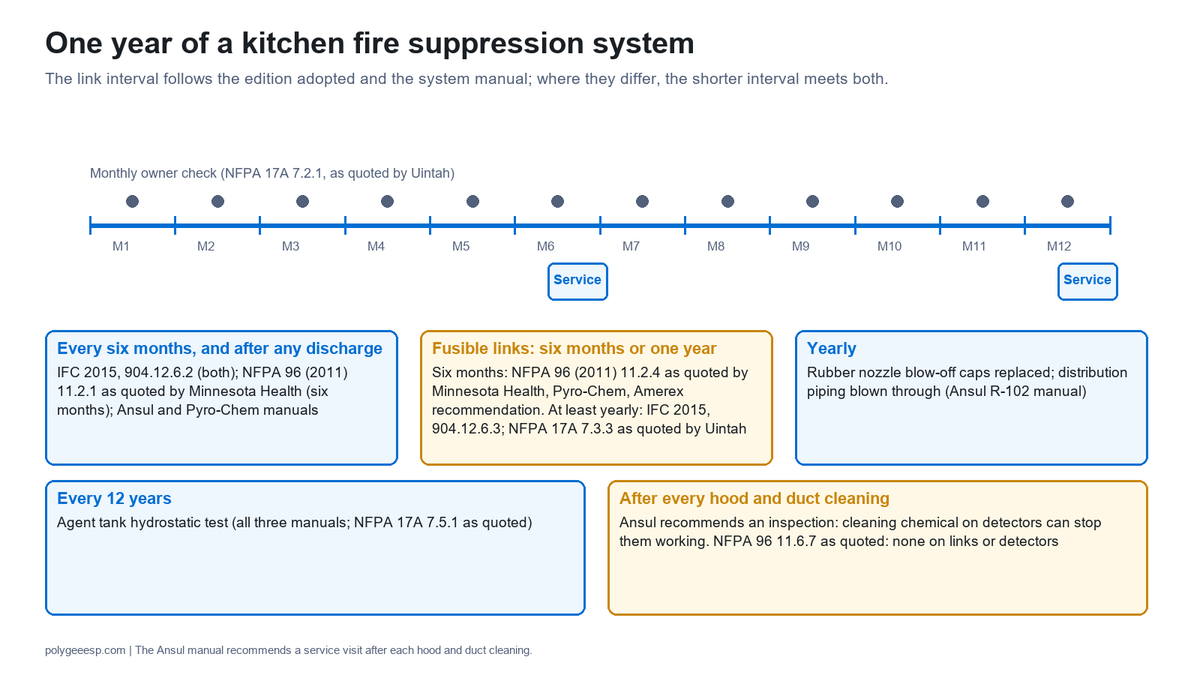
The fusible link interval is where buyers are given two answers, and both are on paper. The NFPA 96 edition quoted by the Minnesota Department of Health says semiannually; NFPA 17A as quoted and the 2015 IFC say at least annually. The Ansul manual has the links replaced at each semiannual service, and Pyro-Chem’s manual says semiannually “per NFPA 96.” Which applies is set by the edition adopted where the kitchen is and by the contractor’s listed manual.
Two scheduling points follow for a kitchen with a precipitator. The duct cleaning and the cell washing are separate jobs from the suppression service, but the cleaning crew’s chemicals reach the same detectors, so the Ansul manual’s advice to service the system after a cleaning is easiest to follow when the suppression visit is booked to follow the cleaning. And Trion’s manual repeats the rule that cooking equipment is not to be operated while its fire-extinguishing system or exhaust system is impaired, which includes the days a precipitator is out for repair with its suppression disconnected. Our exhaust cleaning requirements page covers the duct cleaning side, and our electrostatic precipitator cleaning page the cells.
After a discharge: the hood, the duct and the precipitator
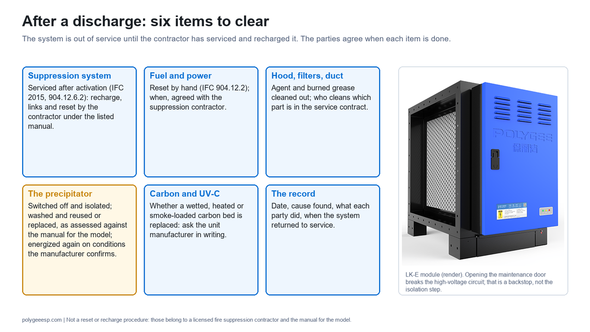
After a discharge the system is out of service until the suppression contractor has serviced and recharged it, the fuel and power to the cooking equipment stay off until reset by hand, and a precipitator in the duct is not energized again until it has been assessed against the manual for its model. The items below are what each party clears; the suppression contractor and the unit manufacturer agree when each is done.
- The suppression system. The 2015 IFC, Section 904.12.6.2, requires service after activation. Recharge, link replacement and reset are the contractor’s, under the listed manual.
- Fuel and power. The reset is manual under IFC 904.12.2; when it is done is agreed with the suppression contractor.
- Hood, filters and duct. Agent and burned grease are cleaned from the cooking area, the plenum and the duct; who cleans which part is written in the service contract.
- The precipitator. Whether cells that agent, water or smoke reached can be washed and reused, or are replaced, is assessed against the manual for the model, with the unit switched off and isolated first. On our units the maintenance door breaks the high-voltage circuit through magnetic switches when opened; that is a backstop, not a substitute for the isolation step. The conditions for energizing the unit again, covering the cells, the insulators and the power section, are confirmed by the manufacturer or its service agent.
- Carbon and UV-C stages. Whether a carbon bed that has been wetted, heated or smoke-loaded is replaced is a question for the unit manufacturer in writing, not one to settle by looking at the bed. UV-C lamps and housings are checked under the manual.
- The record. The date, the cause found, what each party did and when the system was returned to service go into the file with the next service report.
A replacement part after a fire is quoted on its own: the collection cells and the SPP power module are parts we supply separately, and a quotation states which. Whether damage from a fire falls under a warranty is not something this page can answer, and the place to settle it is the written terms of the supply.
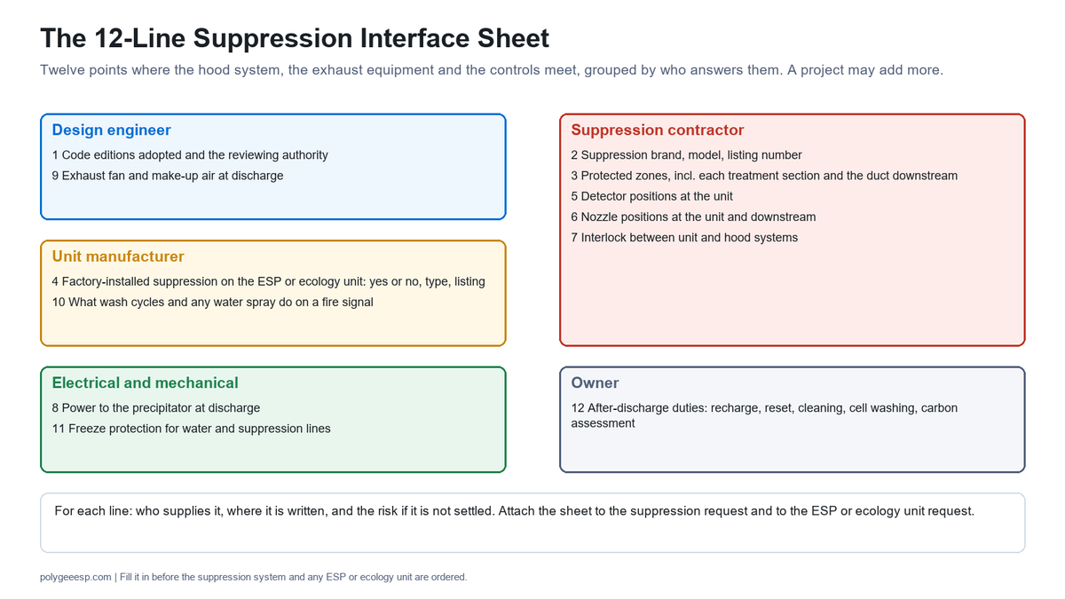
The 12-Line Suppression Interface Sheet
The 12-Line Suppression Interface Sheet lists twelve points where the hood suppression system, the exhaust equipment and the controls meet, chosen for this page, with who supplies each and where it is written; a project may add more. Fill it in before the suppression system and any ESP or ecology unit are ordered, and attach it to both requests for quotation.
| # | Line | Who supplies it | Where it is written | Risk if it is not settled |
|---|---|---|---|---|
| 1 | Code editions adopted (IMC or UMC, IFC, NFPA 96) and the authority that reviews | The design engineer, from the authority | The drawing title block or the code summary | Item numbers and link intervals may be read from the wrong edition |
| 2 | Suppression brand, model and listing number | The suppression contractor | The suppression submittal | Nozzle and detector positions cannot be checked against the listing |
| 3 | Protected zones: appliances, plenum, duct, each treatment section, duct downstream | The suppression contractor | The suppression drawing | A section of the run may be left out of the protection design |
| 4 | Factory-installed suppression on the ESP or ecology unit: yes or no, which type, which listing | The unit manufacturer, in writing per model | The quotation and the unit submittal | Where that edition is adopted, item 10 of IMC 2024, 506.5.2 may be raised at inspection |
| 5 | Detector positions at the unit: below and above, or as the unit’s listing sets | The suppression contractor, with the unit drawing | The suppression drawing | Detection at the unit may not match what its listing or the suppression design expects |
| 6 | Nozzle positions at the unit and downstream, and the access to reach them | The suppression contractor, with the unit drawing | The suppression drawing and the duct drawing | Nozzles may not fit where the duct leaves no room |
| 7 | Interlock between the unit’s suppression and the hood system | The suppression contractor and the electrician | The control drawing | The two systems may not act together |
| 8 | Power to the precipitator at discharge | The electrical designer, with the unit’s power supply data | The control drawing | The precipitator may stay energized during a fire |
| 9 | Exhaust fan and make-up air at discharge | The design engineer, against the listed design and the unit’s fire mode | The control drawing and the sequence of operation | The fan may do the opposite of what the suppression design assumed |
| 10 | What a wash cycle and any water spray do on a fire signal, on units with automatic washing | The unit manufacturer and the electrician | The control drawing | The wash and fire sequences are left undefined |
| 11 | Freeze protection for water and suppression lines | The mechanical contractor | The mechanical drawing | Where that edition is adopted, item 13 of IMC 2024, 506.5.2 may be raised on a cold roof |
| 12 | After-discharge responsibilities: recharge, reset, cleaning, cell washing, carbon assessment | The owner, with each contractor | The service contracts | The kitchen may reopen before the precipitator has been checked |
Key takeaways
- One listed design, three zones: appliances, plenum and duct; any change to the cookline or the duct is a design change for the suppression contractor.
- Four actions from one actuation: detection, release, discharge, and shutoff of fuel or power with a manual reset; a pull station 10 to 20 ft from the exhaust system starts the same actuation (IFC 2015).
- The numbers belong to the manual: link ratings, nozzle coverage and tank sizes differ by brand, and one 360 °F link is rated for different ambients in two manuals.
- Service at least every six months and after any discharge; links every six months or every year depending on the document adopted; and, as the Ansul manual recommends, after every hood and duct cleaning.
- An ESP or ecology unit adds protection of its own: factory-installed suppression in IMC 2024, 506.5.2 item 10, and protection of the unit and the duct downstream in NFPA 96 as summarized by Intertek, MeyerFire and UL; an interlock with the hood system and a shutoff of precipitator power appear in the New York approvals read. Settle each on The 12-Line Suppression Interface Sheet before ordering.
Frequently asked questions
- How does a kitchen fire suppression system work?
- A detector in the hood or duct reaches its rating, a fusible link on a cable or a pneumatic detection tube on the systems read here, and the release either pressurizes a tank of wet chemical agent from a gas cartridge or opens a cylinder already stored under pressure. The agent is pushed through fixed piping to nozzles over the appliances, in the hood plenum and in the duct, where it cools burning grease and forms a soap-like layer on it. At actuation, switches shut off the fuel or electric power to the cooking equipment, and the reset is manual. A pull station near the exit starts the same actuation by hand.
- What is an Ansul system?
- ANSUL is a Tyco Fire Products brand, and the R-102 is its pre-engineered wet chemical restaurant fire suppression system, listed by UL under EX3470 and tested to UL 300. Other listed systems, such as the Amerex KP and the Pyro-Chem Kitchen Knight II, work on the same principle with their own nozzle, tank and link figures.
- How often does a kitchen fire suppression system need to be inspected?
- At least every six months by a qualified person, and after every discharge, under the 2015 International Fire Code and NFPA 96 as quoted by the Minnesota Department of Health; NFPA 17A as quoted adds a monthly check by the owner. Fusible links are replaced every six months under the NFPA 96 edition quoted and at least once a year under NFPA 17A and the 2015 IFC, and agent tanks are hydrostatically tested every 12 years in the manuals read. An inspection after each hood and duct cleaning is recommended in the Ansul manual, because cleaning chemical on the detectors can stop them working.
- Does an electrostatic precipitator in the kitchen exhaust duct need its own fire suppression?
- Under the codes read for this page, yes. The 2024 International Mechanical Code, Section 506.5.2 item 10, requires a pollution control unit to be provided with a factory-installed fire suppression system, and NFPA 96, from its 2017 edition according to Intertek’s update notice, requires air pollution control devices in the duct to be protected by an automatic fire-extinguishing system; as quoted by MeyerFire and UL, that protection extends to the ductwork downstream. The Ansul R-102 manual gives a design for an ESP at the base of a duct but refers pollution control units to its technical services outside its listed design, so the protection is settled between the unit manufacturer, the suppression contractor and the authority having jurisdiction before the unit is ordered.
- Should the exhaust fan stay on when the suppression system discharges?
- The Ansul R-102 and Pyro-Chem Kitchen Knight II manuals say the exhaust fan should stay on, because its draft helps move the agent and cools the plenum and duct, and both systems are listed with or without fan operation; make-up air inside the hood shuts down. Where a pollution control unit is in the duct, its own documents may set a different sequence: one manufacturer’s unit stops the exhaust fan on an internal fire and starts it on an external one, and a New York City acceptance for a precipitator keeps the fan running while cutting power to the precipitator. The sequence for a given kitchen belongs on its control drawing.
Adding an ESP or ecology unit to a protected exhaust run?
Send us the hood length, the exhaust airflow, the duct size at the point where the unit would go, the suppression brand already installed or specified, and the code editions your authority has adopted. You get back the model whose rating covers the airflow, its dimensions and access sides for the nozzle and detector positions, its power supply arrangement for the shutoff, and a written statement of what the model carries and does not carry for fire protection, so lines 4 to 10 of The 12-Line Suppression Interface Sheet can be filled in before anything is ordered. The suppression design, its listing and its installation stay with your suppression contractor.
Send the hood, airflow and suppression details →
The precipitator and its options are set out on our kitchen electrostatic precipitator page, the listing we hold on our UL 867 page, and the installation order of a hood on our commercial kitchen hood installation guide.
Why we write this. Guides to hood suppression systems explain the hood system well; few of the ones we read for this page take up what changes when treatment equipment sits in the duct. Ours starts there, where a precipitator or an ecology unit changes what the suppression drawing has to show, and the questions that change are easier to answer when the documents that raise them are side by side. This page gives no suppression design, no installation step and no figure of ours that is not on our record.
Law is Project Manager at Polygee. Polygee, founded in 2004, manufactures the in-duct electrostatic precipitators, UV-C and activated carbon modules, kitchen ecology units and ESP hoods named here; it does not make or install fire suppression systems. The code text cited on this page was read in the sources listed below, NFPA clauses through the public excerpts named, and the suppression and unit figures are those of the manufacturers whose manuals are listed.
References & further reading
- International Code Council, International Mechanical Code 2024, chapter 5 Exhaust Systems: sections 506.5.2 (items 1, 9, 10, 13), 507.1.1 and 507.2.11; 2021 edition section 506.5.2 item 9 and section 509.1. codes.iccsafe.org
- International Fire Code 2015, section 904.12 (as published by the City of Lawrence, Kansas, Fire Medical): manual actuation, shutoff, portable extinguishers, service and link replacement. lawrenceks.org
- Tyco Fire Products, ANSUL R-102 Restaurant Fire Suppression System Design, Installation, Recharge and Maintenance Manual, UL EX3470, Rev. 11, 2014: PDF pp. 9, 15, 22, 25, 27–31, 95, 99, 159–163 (system description, agent, detectors, links, duct, plenum and precipitator coverage, maintenance). captiveaire.com
- Amerex Corporation, KP Restaurant Fire Suppression System Design, Installation, Maintenance and Recharge Manual, P/N 12385: cylinders, links, duct nozzle, link replacement. s3.amazonaws.com
- Amerex, Zone Defense Restaurant Fire Suppression System specification: pneumatic detection and nozzle spacing. thebigredguide.com
- Tyco Fire Products, PYRO-CHEM Kitchen Knight II Restaurant Fire Suppression System Technical Manual, UL EX3830, Part No. 551274-06, 2014: cylinders, links, duct nozzles, precipitators, maintenance. absupply.net
- Amerex, “What is a Class K fire?”, technical note TT42-1024: the 1994 revision of UL 300. amerex-fire.com
- Intertek, Standards Update Notice, NFPA 96 (2021 edition): clauses 9.3.1.3, 10.1.3 and 10.2.3.1 and the editions that added them. intertek.com
- MeyerFire, “Protection for Kitchen Exhaust Filtration Unit”, 2020: NFPA 96 (2017) 9.3.3 and 9.3.3.1. meyerfire.com
- UL Solutions, “Pollution Control Units for Commercial Cooking Systems: Then and Now”, 2019: UL 8782 and downstream duct protection. ul.com
- Minnesota Department of Health, “Protection of Kitchen Cooking Equipment”: NFPA 96 (2011) 11.2.1, 11.2.4, 11.6.7 as quoted. health.mn.gov
- Uintah Fire Suppression Special Service District, “Wet Chemical Extinguishing Systems (NFPA 17A)” checklist: clauses 7.2.1, 7.3.3 and 7.5.1 as quoted. uintahfiredistrict.gov
- Greenheck, Grease Trapper ESP Installation, Operation and Maintenance Manual, Rev. 3, July 2019: fire system, controller fire input. greenheck.com
- Captive-Aire Systems, Technical Manual for Installation, Operation and Maintenance of the Electrostatic Precipitator: fire extinguishing options, internal and external fire modes, odor media. captiveaire.com
- New York City Fire Department, Bureau of Fire Prevention, Certificate of Approval 5753, Captive-Aire pollution control unit, 2025. captiveaire.com
- New York City Department of Buildings, MEA 288-01-E Vol. 2, Trion electrostatic precipitators. nyc.gov
- Trion, KES Series Installation, Operation and Maintenance Manual (hosted by Johnson Controls): fire suppression recommendation and impaired-system rule. docs.johnsoncontrols.com
- US Fire Administration, National Fire Data Center, “Restaurant Fires”, Topical Fire Research Series, vol. 4 issue 3, October 2004 (2002 data). usfa.fema.gov
Related reading
- Commercial kitchen hood fire suppression requirements: the code clauses in the order a plan reviewer checks them.
- Pollution control unit: what the term covers, the stages inside one, and what Section 506.5.2 attaches to each.
- Fire dampers in kitchen extract: what three codes say about a damper in a grease duct, and what does the separating instead.
- Commercial kitchen ventilation system: the six parts of the system and the clause that governs each.