

A commercial kitchen hood installation is the work of hanging a hood at the height and overhang the code fixes, supporting it from the structure and, for the Type I hood that grease and smoke call for, connecting it to a welded grease duct and a fan built or listed for the duty, fitting its listed filters and interlocks, tying in the make-up air and the fire suppression, and proving by test that it captures what the cookline produces. Seven steps, one permit, one chapter of the International Mechanical Code.
Half of the people who search for a commercial kitchen hood installation are looking for someone to do it. This page is for the other half, and for the first half once the installer is chosen: the owner, the general contractor, the consultant and the dealer who have to recognize a correct installation when they see one, sign it off and pay for it. It takes the seven steps in the order they happen on site, gives each its governing section in the 2021 International Mechanical Code (IMC), names the trade that owns it, and ends with a sign-off sheet to fill before the final payment.
This page helps you decide whether the installation you are about to accept contains everything the code asks of it, which contractor is answerable for each part, and what has to be tested before the authority having jurisdiction (AHJ) gives final approval. It does not set the exhaust rate, which our hood CFM requirements guide covers, and it does not reproduce the clearance table, the grease duct construction rules or the suppression design, each of which has its own page here. One disclosure before the steps: Polygee builds in-duct electrostatic precipitators and a hood with the ESP cells built into the canopy. We do not install hoods, fabricate grease duct or fit suppression systems, and nothing on this page is a compliance determination; the AHJ applies the edition it has adopted.
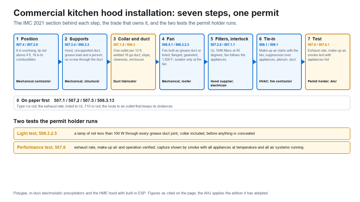
| Question | Short answer |
|---|---|
| What does the installation include? | Seven steps: position, supports, collar and grease duct, fan, filters and interlocks, make-up air and suppression tie-in, performance test. In the IMC: Sections 507.4 and 507.2.6, 507.2.4 and 506.3.3, 507.1.5 and 506.3, 506.5.1 and 506.3.2.3, 507.2.8 and 507.1.1, 508 and 509, and 507.6 |
| Who does it? | The hood supplier delivers a labelled hood; the mechanical contractor hangs it, runs the duct and sets the fan; a duct fabricator welds the grease duct; a licensed electrician wires the fan, lights and interlock; a fire suppression contractor installs the system under its listing; the permit holder runs the two tests; the AHJ approves |
| What is fixed before the hood is hung? | Whether the hood is Type I, the exhaust rate, whether the hood is listed to UL 710, and the route from the collar to an outlet that keeps its distances |
| What is tested? | Every grease duct joint by a 100 W light test before concealment, and the finished system by a performance test of exhaust rate, make-up air and operation, with capture verified by smoke, before final approval |
| Where does the ESP come in? | Built into the hood, as our HME canopy, the same seven steps apply plus a 380 V supply, a drain, front access to the cells and a fan decision on the quotation; in the duct, as an in-duct unit, it enters at Steps 3 and 4 with the pollution control unit requirements of Section 506.5.2 |
| What about the UK? | DW/172 instead of a code: 250 mm overhang, 450 mm from separator to cooking surface, a fully welded 1.2 mm or 1.6 mm duct where grease-tightness is required, access doors at 2 m centers where no cleaning specification exists, a gas interlock to BS 6173, and a clause 28.2 commissioning record |
| Quick specs on this page | Figure | Basis |
|---|---|---|
| Canopy overhang and height | Inside lower edge at least 6 in (152 mm) beyond the appliance on every open side; front lower lip not more than 4 ft (1,219 mm) above the cooking surface | IMC 2021 Section 507.4.1 |
| Hood clearance to combustibles | Not less than 18 in (457 mm), with the gypsum board exception and the UL 710 listing exception | IMC 2021 Section 507.2.6 |
| Hood exhaust outlets | Each outlet serves not more than a 12 ft (3,658 mm) section of hood | IMC 2021 Section 507.1.5 |
| Grease duct light test | A lamp of not less than 100 W passed through the whole duct before use or concealment, every welded joint and the hood-to-duct connection included | IMC 2021 Section 506.3.2.5 |
| Fan connection | Flanged and gasketed; bolted for side-inlet and in-line fans; gaskets rated for continuous duty at 1,500 °F (816 °C); a vibration isolator only at the fan inlet or outlet | IMC 2021 Sections 506.3.2.3 and 506.3.2.4 |
| Grease filters | Listed to UL 1046, at not less than 45 degrees from horizontal, with a drip tray; lowest edge 0.5 ft, 2 ft or 3.5 ft above the cooking surface by appliance type | IMC 2021 Section 507.2.8 and Table 507.2.8 |
| Fan interlock | The fan starts when any appliance needing the Type I hood is turned on, or the appliances cannot run without it; sensor-activated fans start within 15 minutes; the interlock may not depend on the suppression system | IMC 2021 Section 507.1.1 |
| Performance test | Exhaust rate, make-up air and operation verified before final approval; capture and containment verified by smoke with all appliances at temperature | IMC 2021 Sections 507.6 and 507.6.1 |
| Polygee HME hood with built-in ESP | 12 models, 1,500 to 2,400 mm long, 1,100 or 1,300 mm deep, ESP rated 3,000 to 4,800 m³/h (1,766 to 2,825 cfm), 380 V 50 Hz, 98.0 to 98.1% in third-party tests; fan confirmed on the quotation | Polygee model tables and test reports |
- What a commercial kitchen hood installation includes, and who does which part
- Step 0: four decisions made on paper before anything is hung
- Step 1: position the hood to three numbers and one wall
- Step 2: support it for four loads, not one
- Step 3: the collar, the grease duct and the light test
- Step 4: the fan, and the one place a flexible connector is allowed
- Step 5: filters, drains, lights and the interlock
- Step 6: make-up air and fire suppression are tied in, not added
- Step 7: the performance test, and what the sign-off rests on
- Where the electrostatic precipitator enters the installation
- A worked example: a 10 ft heavy-duty line, installed
- The UK reading: DW/172 instead of a code
- What an installation price is made of
- Eight installation errors that cost a re-inspection
- The Seven-Step Hood Installation Sign-Off Sheet
- Where this guide stops
- Buyer record and key takeaways
- Frequently asked questions
What a commercial kitchen hood installation includes, and who does which part
An installation is seven steps, on most projects under one mechanical permit, and projects go wrong when the seven steps are bought from six different parties and no one holds the list. The hood arrives with the kitchen equipment, the duct with the mechanical contractor, the fan with whoever is on the roof, the suppression with a fire contractor who comes later, the electrical with the electrician, and the make-up air with the HVAC package. Each does its own step correctly and the system still fails the performance test, because the steps were sized or sequenced to different assumptions.
Section 507.1 of the IMC is the sentence that makes it one system: where a Type I hood is installed, the installation of the entire system, including the hood, ducts, exhaust equipment and makeup air system, shall comply with Sections 506, 507, 508 and 509. The hood is the head of a chain, and the inspector checks the chain. Our guide to the six parts of a commercial kitchen ventilation system maps that chain part by part; this page follows the same chain in the order an installer works it.
| Step | What is done | Governing section, IMC 2021 | Who owns it | What you see at the end of the step |
|---|---|---|---|---|
| 0 Paper | Hood type, exhaust rate, listed or unlisted, route to the outlet, permit | 507.1, 507.2, 507.5, 506.3.13 | Owner, kitchen designer, mechanical engineer; the AHJ issues the permit | A permit set with the hood schedule, the rate and the duct route |
| 1 Position | Overhang, lip height, clearance to the wall and ceiling, penetration detail | 507.4, 507.2.6, 507.2.7 | Mechanical contractor, against the hood supplier’s drawing | A hood whose lip, overhang and wall gap measure to the drawing |
| 2 Supports | Noncombustible hangers from structure, sized for hood, duct, grease and people | 507.2.4, 506.3.3 | Mechanical contractor; structural engineer where the load is new | Hangers to structure, not to the ceiling grid; no fastener through the duct wall |
| 3 Collar and duct | Collar per 12 ft of hood; welded grease duct, sloped, with cleanouts, enclosed where it leaves the room; light test | 507.1.5, 506.3.1 to 506.3.12 | Duct fabricator and mechanical contractor; the permit holder runs the light test | A liquid-tight duct, tested with a lamp before the ceiling closes |
| 4 Fan | Fan built as grease duct or listed for the duty, flanged and gasketed connection, isolator only at the fan, cleanouts each side of an in-line fan | 506.5.1, 506.3.2.3, 506.3.2.4, 506.3.8.2 | Mechanical contractor; roofing contractor for the curb | A fan selected at the design airflow and the whole run’s static pressure |
| 5 Filters and interlock | Listed grease filters at 45 degrees with a drip tray; gutters to a receptacle; lights; fan interlocked with the appliances | 507.2.8, 507.2.9, 507.1.1 | Hood supplier supplies; licensed electrician wires | Listed filters, removable for cleaning; a fan that starts with the appliances, or an interlock that stops them without it |
| 6 Tie-in | Make-up air interlocked with the exhaust; suppression over the appliances, plenum and duct | 508.1, 509.1 | HVAC contractor; fire suppression contractor under the system listing | Make-up air that starts with the fan; a suppression certificate |
| 7 Test | Exhaust rate, make-up air and operation verified; capture and containment by smoke | 507.6, 507.6.1 | Permit holder, witnessed by the AHJ | A test record, and final approval |
The table is the order of the rest of this page. The trade column is the usual division; on a given project the contract decides who is the permit holder, and the permit holder is the one the code names for the two tests.
Step 0: four decisions made on paper before anything is hung
Four things are fixed before the hood is ordered, because each of them changes what the installer builds. None of them is an installation step, and all of them are the reason an installation passes or fails.
Whether the hood is Type I. Section 507.2 puts a Type I hood over appliances that produce grease or smoke, which the code groups as medium-, heavy- and extra-heavy-duty cooking, and Section 507.1 makes the whole hood Type I where any appliance under it needs one. The single exception is an electric appliance that an approved testing agency has shown to release 5 mg/m³ or less of grease at 500 cfm under UL 710B. Heat and steam alone call for a Type II hood under Section 507.3, unless their loads are taken into the HVAC design or a separate removal system, with a different duct and none of the grease provisions on this page; the appliance list that decides it is in our Type 1 versus Type 2 guide. An extra-heavy-duty hood, over solid fuel, may not cover lighter appliances and goes to its own exhaust system under Section 507.2.2; that case is in solid fuel cooking exhaust requirements.
The exhaust rate. Section 507.5 sets the minimum net airflow by duty tier and hood style, with the heaviest appliance under the hood setting the rate for the whole hood, and a hood listed to UL 710 using the rate on its listing instead. The rate is settled here because Step 3 sizes the duct from it, Step 4 selects the fan to it, Step 6 balances the make-up air against it and Step 7 measures it. Our hood CFM requirements guide gives the table.
Whether the hood is listed. A factory-built hood listed and labelled to UL 710 and installed to Section 304.1 is excused by the first exception to Section 507.1 from eight sections: 507.1.5, 507.2.3, 507.2.5, 507.2.8, 507.3.1, 507.3.3, 507.4 and 507.5. In installation terms that means the listing, not the code table, gives the outlet spacing, the material, the welds, the filters, the overhang and height, and the rate. The installer therefore works from the listing page and the manufacturer’s instructions for a listed hood, and from the sections below for an unlisted one. Ask for the listing page, not the brochure.
The route to the outlet. The collar position, the duct route through the building and the outlet position are drawn before the hood is hung, because the outlet has distances to keep, 40 in above the roof, 10 ft from property lines and adjacent buildings, and 10 ft from or 3 ft above any air intake, and the route decides how much of the duct has to be enclosed. The distances are in exhaust termination requirements; the eleven points a plan reviewer walks across the whole set are in hood code requirements.
Step 1: position the hood to three numbers and one wall
The hood goes where three code figures and the wall behind it put it, and the installer measures all four before the first hanger is set. Section 507.4.1 requires the inside lower edge of a canopy hood to overhang or extend a horizontal distance of not less than 6 in (152 mm) beyond the edge of the top horizontal surface of the appliance on all open sides, and limits the vertical distance between the front lower lip of the hood and that surface to not more than 4 ft (1,219 mm). Where the hood is closed to the appliance side by a noncombustible wall or panel, it may sit flush with the outer edge of the cooking surface on that side. A noncanopy hood, under Section 507.4.2, sits not more than 3 ft (914 mm) above the cooking surface with its edge set back not more than 1 ft (305 mm) from the edge of the cooking surface.
Neither figure says where to hang the hood; they bound the answer. The height the trade works to, written into municipal design guidance and manufacturers’ installation manuals rather than the code, puts the bottom edge of a canopy about 6 ft 6 in to 7 ft above the finished floor, which with a 36 in cooking surface lands the lip at or just inside the 4 ft limit. The arithmetic is done per appliance, because the 4 ft is measured to the cooking surface and a taller appliance shortens it; the table of every distance around the hood, with its source and its exception, is in hood clearance requirements.
The wall decides the fourth figure. Section 507.2.6 requires a Type I hood to be installed with a clearance to combustibles of not less than 18 in (457 mm). Its first exception is the one many kitchens use: no clearance is required from gypsum wallboard, or from cementitious wallboard at least 1/2 in thick, attached to noncombustible structures, provided a smooth, cleanable, nonabsorbent and noncombustible material is installed between the hood and the board over an area extending at least 18 in in all directions from the hood. A stainless wall panel behind and beside the hood is how that exception is usually met. The second exception lets a hood listed to UL 710 for a smaller clearance be installed at the clearance in its listing. What the installer needs before the hood is hung is therefore the wall section, not the hood drawing: gypsum board on wood studs is combustible construction under this section and takes the full 18 in.
Two further positions are settled at this step. Where a Type I hood or any part of it penetrates a ceiling, wall or furred space, Section 507.2.7 sends it to the grease duct enclosure rules of Section 506.3.11, and states that a field-applied grease duct wrap may not be used to satisfy that requirement at the hood. And where vented fuel-burning appliances share the room, Section 507.1.3 requires provisions so that the hood system does not interfere with the normal operation of their vents; a hood that starves a water heater flue is an installation fault, not an appliance fault.
Step 2: support it for four loads, not one
Section 507.2.4 is two sentences, and the second is the one that gets under-read. Type I hoods shall be secured in place by noncombustible supports, and the supports shall be adequate for the applied load of the hood, the unsupported ductwork, the effluent loading and the possible weight of personnel working in or on the hood. Four loads: the hood, the duct the hood carries until the duct’s own hangers take over, the grease that accumulates, and a person. A hood hung from the ceiling grid, or from hangers sized to the catalog weight of the empty hood, has not been checked against the last three.
The grease duct carries the same rule in Section 506.3.3: bracing and supports of noncombustible material, securely attached to the structure, designed to carry gravity and seismic loads within the stress limits of the International Building Code, and with no bolts, screws, rivets or other mechanical fasteners penetrating the duct wall. The last clause is the one an inspector looks for with a flashlight, because a self-tapping screw through a grease duct is a grease leak and a fire path in one.
Where anything heavier than duct is to hang on the run, the weights go to whoever owns the structure before the layout is fixed, as three separate items rather than an average. Our ecology unit installation guide works that through for a three-stage train, where the carbon module is the heaviest single item; the principle is the same for any in-duct unit, and for a hood with equipment built into the canopy, whose weight is taken from the model drawing rather than from the hood schedule.
Step 3: the collar, the grease duct and the light test
The hood meets the duct at the collar, and from the collar to the fan the installation is a grease duct, governed by Section 506.3 in full. Three things are fixed at the hood end, the duct is built to six rules, and the whole is tested with a lamp before anyone closes a ceiling.
At the hood end
Section 507.1.5 places the exhaust outlets within the hood so as to optimize the capture of particulate matter, and limits each outlet to serving not more than a 12 ft (3,658 mm) section of hood; a hood longer than 12 ft has as many outlets as it takes for no outlet to serve more than 12 ft, each with its own duct connection, or the arrangement its listing was tested with. Section 507.2.5 requires the external joints, seams and penetrations of a Type I hood to be made with a continuous external liquid-tight weld or braze to the lowest outermost perimeter, and internal seams need not be welded but are sealed grease-tight. Section 506.3.2.2 then governs the duct-to-hood joint itself: a continuous internal or external liquid-tight welded or brazed joint, smooth, accessible for inspection and without grease traps, with two exceptions, a vertical collar connection in the top plane of the hood made with 1 in welded flanges, a gasket rated 1,500 °F and welded stud bolts at not more than 4 in centers, or a listed duct-to-hood collar connection installed to Section 304.1. A self-tapping screw connection is neither. And the duct that leaves the collar is a Type I grease duct under Section 506.3.1.1: steel at least 0.0575 in thick, 16 gage, or stainless steel at least 0.0450 in, 18 gage.
Six rules the duct is built to
Our grease duct requirements guide takes these in the order a drawing is reviewed, with the differences from NFPA 96 on each; here is what the installer is held to on site.
| Rule | What the installer does | IMC 2021 | What you check |
|---|---|---|---|
| Velocity | Builds the duct to carry the design airflow at not less than 500 fpm (2.5 m/s); transitions up to 3 ft long at the hood and fan are excepted | 506.3.4 | The duct cross-section is not larger than the airflow divided by 500; a larger duct is a grease trap, as exhaust duct size explains |
| Slope | Slopes the duct not less than 1/4 in per foot (2 percent) toward the hood or a grease reservoir; 1 in per foot (8.3 percent) where a horizontal run exceeds 75 ft | 506.3.7 | A level laid on the horizontal run; no low point without a reservoir |
| Cleanouts | Fits cleanouts on sections not reachable from the hood or the outlet, not more than 20 ft apart and within 10 ft of any change of direction greater than 45 degrees; horizontal cleanouts at least 12 in by 12 in, at least 1 in from the duct edge, at every reservoir and within 3 ft of a horizontal-discharge fan; doors of duct-thickness steel, liquid-tight, with gaskets rated 1,500 °F and no fasteners through the duct | 506.3.8, 506.3.9 | Count the cleanouts against the drawing; open one |
| Clearance | Keeps unenclosed duct and exhaust equipment not less than 18 in (457 mm) from combustible construction and not less than 3 in (76 mm) from noncombustible construction and gypsum board on noncombustible framing | 506.3.6 | A tape measure at the closest point to any wood |
| Enclosure | Encloses the duct from the point it penetrates a ceiling, wall, floor or concealed space to the outlet, in a shaft, a field-applied enclosure listed to ASTM E2336, which covers the duct continuously on all sides from where it originates to the outlet terminal, or a factory-built assembly listed to UL 2221; rated not less than the assembly penetrated and not less than 1 hour; one grease duct per enclosure; inside a shaft the duct keeps 18 in to combustible and 6 in to noncombustible construction and gypsum board (506.3.11.1); through an exterior wall only where unprotected openings are permitted; no fire or smoke dampers in a grease duct | 506.3.11 | The listing of the wrap or the shaft detail; a tight-fitting sliding or hinged access door, rated equal to the enclosure, at every cleanout inside it, marked ACCESS PANEL. DO NOT OBSTRUCT. (506.3.12) |
| Separation | Gives each Type I hood its own duct system unless the conditions for interconnection are all met | 506.3.5 | Two hoods on one riser have the engineer’s note that lists the conditions |
The light test, before anything is concealed
Section 506.3.2.5 is the test few owners budget for and the one that decides whether a welded duct is actually liquid-tight. Prior to the use or concealment of any portion of a grease duct system, a leakage test shall be performed: a lamp with a power rating of not less than 100 W, open so as to emit light equally in all directions perpendicular to the duct walls, is passed through the entire section of ductwork, and every welded and brazed joint is shown to be liquid-tight. The test covers the entire system including the hood-to-duct connection, may be done in sections provided every joint is tested, and for listed factory-built grease duct is limited to the joints assembled in the field. Ducts installed in shafts or covered by wraps that prevent inspection on all sides count as concealed, so the test is done before the wrap goes on. The permit holder is responsible for providing the equipment and performing the test, and that is why the sign-off sheet at the end of this page asks who the permit holder is on the first line.
Step 4: the fan, and the one place a flexible connector is allowed
The fan is part of the grease duct system, and the IMC treats its connection with the same care as a duct joint. Section 506.5.1 requires the housing of an exhaust fan serving a Type I hood to be built to the grease duct material rule of Section 506.3.1.1 unless the fan is listed and labelled to UL 762, now UL 705 Supplement SC, and Section 506.5.1.1 puts the motor outside the exhaust airstream; the three fan types, upblast, utility set and in-line, and the NFPA 96 provisions for a hinged roof fan with a flexible weatherproof cable and hold-open retainers, are in our exhaust fan requirements guide. Two installation rules sit at the connection itself.
Section 506.3.2.3 fixes how the duct meets the fan: flanged and gasketed at the base of the fan for a vertical-discharge fan; flanged, gasketed and bolted to the inlet for a side-inlet utility fan; flanged, gasketed and bolted to both inlet and outlet for an in-line fan; and the gasket and sealing materials rated for continuous duty at not less than 1,500 °F (816 °C). A slip joint with sealant at the fan is not a compliant connection, whatever the sealant’s datasheet says about kitchens.
Section 506.3.2.4 is the rule that catches many retrofits. A vibration isolation connector may be a noncombustible packing in a metal sleeve joint of approved design or a coated-fabric flexible duct connector listed and labelled for the application, and vibration isolation connectors shall be installed only at the connection of a duct to a fan inlet or outlet. There is one place on the whole run where a flexible connector belongs, and it is not in the middle of a riser or at a unit that was added later. An in-line fan also takes a cleanout on each side within 3 ft of its duct connections under Section 506.3.8.2, and an in-line fan not located outdoors sits in a room with the same fire-resistance rating as the duct enclosure, with access for service and cleaning, under Section 506.5.1.2.
What the code never states is the number the fan is selected to: the static pressure at the design airflow. The hood, the duct, every fitting, the outlet and any treatment stage each add resistance, and a fan picked from the hood rate alone delivers less than the design rate on the day of the test. Where an in-duct electrostatic precipitator is on the run, our complete in-duct unit with its airflow distribution plate adds 150 Pa or less, about 0.6 in. w.g., and that figure goes on the fan schedule before the fan is bought, not after the smoke test fails.
Step 5: filters, drains, lights and the interlock
The hood is finished from the inside out: the grease filters, the drains that collect what they shed, the lights, and the electrical interlock that makes the hood run whenever the cookline does. Three of these come from the hood supplier and one from the electrician, and the inspector checks all four from the floor.
Filters. Section 507.2.8 requires Type I hoods to be equipped with grease filters listed and labelled to UL 1046, with access for cleaning or replacement, and sets the minimum distance from the lowest edge of the filter to the cooking or heating surface in Table 507.2.8: 0.5 ft over appliances without exposed flame, 2 ft over exposed flame and burners, 3.5 ft over exposed charcoal and charbroil-type appliances. Under Section 507.2.8.1 the filters pass the required airflow at rates not exceeding those they were designed or approved for, are removable without separate tools unless designed to be cleaned in place, are sized to go through a dishwasher or pot sink where they are cleaned, and are arranged or fitted with drip-intercepting devices so that grease does not drip onto food or preparation surfaces; under Section 507.2.8.2 they are installed at an angle of not less than 45 degrees from the horizontal with a drip tray beneath the lower edge. A mesh filter on its own does not meet the listing requirement; what does, and what the filters catch and let through, is in grease filter requirements and ESP versus baffle filter.
Drains and labels. Section 507.2.9 requires the grease gutters of a Type I hood to drain to an approved collection receptacle that is fabricated, designed and installed to allow access for cleaning. Section 507.2.1 requires a Type I hood to bear a label stating the minimum exhaust flow rate in cfm per linear foot that provides capture and containment for the appliances served, by duty classification; the label is the first thing the inspector reads against the permit set. Section 507.1.4 asks that the hood be designed to allow thorough cleaning of the entire hood, which is the clause behind the grease-tight internal seams and the removable panels.
The interlock. Section 507.1.1 is where the electrician earns the inspection. The exhaust fan serving a Type I hood shall have automatic controls that activate the fan when any appliance requiring the hood is turned on, or an interlock that prevents those appliances from operating when the fan is off. Where temperature or radiant energy sensors are used to activate the fan, the fan shall start not more than 15 minutes after the first appliance served by the hood is turned on, and where several hoods share one exhaust system such sensors go in each hood, reachable from the hood outlet or a cleanout. The interlock shall not extinguish standing pilot burners, and it shall not involve or depend on any component of the fire-extinguishing system. The same section allows the net exhaust volume to be reduced under part-load cooking where engineered or listed variable-speed controls maintain capture, which is the demand control case. In the UK the gas side of the same idea is a BS 6173 interlock on the extract and supply fans, covered in gas interlock in a commercial kitchen.
Step 6: make-up air and fire suppression are tied in, not added
Two systems are connected to the hood that were designed by other people, and the installation is not complete until both run with it.
Make-up air. Section 508.1 requires makeup air to be supplied during the operation of commercial kitchen exhaust systems, in an amount from all sources approximately equal to the exhaust for all exhaust systems in the building, without reducing the effectiveness of the exhaust, by gravity or mechanical means, with mechanical makeup air automatically controlled to start and operate simultaneously with the exhaust system, and with the intake opening locations complying with Section 401.4. Section 508.1.1 holds the temperature difference between the makeup air and the conditioned space to 10 °F (6 °C) unless the HVAC system has the capacity to absorb the added load, and Section 508.1.2 requires the design plans to carry an outdoor air balance schedule. What the installer delivers at this step is the interlock, the balance and the intake position; the four routes replacement air can take and what happens behind the hood when it is short are in makeup air requirements.
Fire suppression. Section 509.1 requires cooking appliances that need a Type I hood under Section 507.2 to be provided with an approved automatic fire suppression system complying with the International Building Code and the International Fire Code. The fire code then asks for a system listed to UL 300 where it is a pre-engineered wet or dry chemical system, a manual pull station, an automatic fuel and power shutoff, and service at least every six months; the system protects the appliances, the hood plenum and the duct, and is installed by a fire suppression contractor under the system’s own listing, with the hood manufacturer’s nozzle penetrations made grease-tight as Section 507.2.5 requires. The suppression contractor needs the finished hood and the appliance layout, which is why this step follows Step 5 and not the other way round; what the fire plan reviewer reads, and where an in-duct unit needs protection of its own, is in hood fire suppression requirements. Note the line in Section 507.1.1 again: the appliance interlock may not depend on any part of this system, so the two are wired separately even though the same electrician does both.
Step 7: the performance test, and what the sign-off rests on
No test, no approval. Section 507.6 requires a performance test to be conducted upon completion and before final approval of the installation of a ventilation system serving commercial cooking appliances, and names what it verifies: the rate of exhaust airflow required by Section 507.5, the makeup airflow required by Section 508, and proper operation as specified in the chapter. The permit holder furnishes the test equipment and devices.
Section 507.6.1 sets the conditions of the capture and containment test, and they are the conditions a kitchen actually runs under: all appliances under the hood at operating temperatures, all sources of outdoor air providing makeup air for the hood operating, and all sources of recirculated air conditioning the space operating. Capture and containment is verified visually, by observing smoke or steam produced by actual or simulated cooking, such as from smoke generators. A test done with cold appliances, or with the make-up air unit not yet commissioned, or with the dining room air handler off, is not the test the code describes, and a hood that captures under those conditions can spill under the real ones.
Three records close the step: the airflow measurement at the design rate, the make-up air measurement against the balance schedule, and the smoke test witnessed. In the UK the same evidence is the DW/172 clause 28.2 commissioning record, which asks for the flow verified at the canopy itself and not only at the fan, and the total system pressure drop, which is the figure that tells you whether the fan was selected to the whole run. Once the permit closes, the operating obligation begins: NFPA 96 sets the inspection schedule for grease accumulation by cooking type, and what each inspection tier covers is in exhaust cleaning requirements.
Where the electrostatic precipitator enters the installation
We make this equipment, so this section is written with the disclosure in front: an electrostatic precipitator is not required by any of the seven steps above. It is fitted where a landlord, a neighbor, a council or a wall termination’s nuisance clause makes the discharge the problem rather than the capture. It enters the installation by one of two routes, and each adds items to the sign-off sheet.
Route 1: the ESP is built into the hood
Our HME hood with built-in ESP is built as a Type I canopy, in 12 models from 1,500 to 2,400 mm long and 1,100 or 1,300 mm deep, wall-mounted or island, with the collector cells inside the canopy instead of in a separate duct unit. Steps 0 to 7 apply to it exactly as to any other Type I hood: the overhang and lip height of Section 507.4.1, the 18 in of Section 507.2.6 with its exceptions, the supports, the welded collar, the light test, the listed fan, the UL 1046 filters ahead of the cells, the interlock, the suppression and the smoke test. Its ESP airflow rating, 3,000 to 4,800 m³/h (1,766 to 2,825 cfm) across the 12 models, is the rating of the cells and is matched to the hood’s exhaust rate; it is not the code exhaust rate, which still comes from Section 507.5 or the listing. Four items are added to the installation:
- A supply for the ESP section. All 12 models take 380 V 50 Hz, wired by the electrician on its own circuit and isolator, separate from the fan and lights.
- A drain. The cells collect liquid grease, and the hood’s oil drainage goes to a receptacle that can be cleaned, as Section 507.2.9 asks of the grease gutters.
- Front access to the cells. The cells are withdrawn from the front for washing, so the space in front of the hood is kept clear to the cell length and nothing is mounted across the face. The exact figure comes with the model drawing.
- The fan decision. Whether the exhaust fan is supplied with the hood is confirmed on the quotation; it is not assumed either way, and the fan is still selected to the whole run’s static pressure at Step 4.
The duct flange is 400 by 400 mm on every model except the HME1500, at 310 by 310 mm, and the transition from the flange to the grease duct is a Section 506.3.4 transition, up to 3 ft, designed not to trap grease. The weight for Step 2 is taken from the model drawing, not the hood schedule. Which listings each model carries and which it does not is stated in writing before the order, so that the AHJ reviews the hood against its documents and not against a brochure.
Route 2: the ESP is on the duct
An in-duct electrostatic precipitator, or the three-stage kitchen ecology unit with UV-C and carbon behind it, enters at Steps 3 and 4 and brings Section 506.5.2 with it: the 2021 IMC gives pollution control units fifteen requirements of their own, from a UL 8782 listing and a UL 762 fan to a pressure differential alarm, factory-installed suppression, a drain through a grease interceptor and a duct connection per Section 506.3.2.3 with a transition that slopes toward the cabinet drain pan for at least 18 in where washing can carry water over. We hold UL 867 on our listed in-duct models and no UL 8782 listing, and say so. The fifteen items read as supplier questions, and which fall to the engineer, the fire contractor and the plumber rather than to the unit supplier, are in our six-part system guide; the straight run, the weights as three point loads, the 150 Pa or less the complete in-duct unit adds to the fan, and the D = 1,000 mm service clearance the UV-C and carbon modules publish are in ecology unit installation. The order of stages, hood filters first, then the precipitator, then any odor stage, is in kitchen exhaust filtration.
On the in-duct route the unit changes three of the seven steps: its supports, drain and transition at Step 3, its resistance in the fan total at Step 4, and a second protected item on the suppression drawing at Step 6, under Section 506.5.2 item 9. On the built-in route the canopy is protected as a Type I hood and the four items above are added; how the suppression covers that canopy is settled with the fire contractor against the hood’s documents. On either route the performance test at Step 7 is the same test, run on the final configuration, and it is the reason the resistance figure goes on the fan schedule at the start and not in a change order at the end.
A worked example: a 10 ft heavy-duty line, installed
The example is the same line our six-part guide uses, followed through the seven installation steps: a wall-mounted canopy over a gas charbroiler and a wok range, no solid fuel, in a US jurisdiction on the 2021 IMC, hood unlisted. It is dimensional arithmetic with the code figures and our published equipment figures, not a design; every number on a real project is the engineer’s.
| Step | The figure in the example | Where it comes from |
|---|---|---|
| 0 Paper | Type I, because the charbroiler and wok produce grease and smoke. Heavy duty, unlisted wall canopy: 400 cfm per linear foot. Appliance line 9 ft long; hood 10 ft long to give 6 in of overhang at each open end; 10 ft × 400 = 4,000 cfm, about 6,800 m³/h. Outlet on the roof, 40 in above it and 10 ft from the nearest intake | IMC 507.2, 507.5.2, 507.4.1, 506.3.13 |
| 1 Position | Inside lower edge 6 in beyond the appliance front and both ends; lip not more than 4 ft above the 36 in cooking surface, so the lip is at or below 7 ft above the floor; the wall behind is gypsum board on steel studs with a stainless panel extending 18 in beyond the hood on every side, which meets the first exception to 507.2.6; the hood does not enter the ceiling | IMC 507.4.1, 507.2.6 |
| 2 Supports | Hangers from the roof structure, noncombustible, sized for the hood, the riser down to the first duct hanger, the grease load and a 100 kg person on the hood, to the structural engineer’s approval; no fastener through the duct | IMC 507.2.4, 506.3.3 |
| 3 Collar and duct | One collar, because the hood is under 12 ft; a welded 16 gage riser; cross-section no larger than 4,000 ÷ 500 = 8.0 ft², for example 24 in by 40 in, which gives 600 fpm; slope 1/4 in per foot on the short horizontal to the roof; a cleanout within 10 ft of the elbow; because the riser penetrates the ceiling, an enclosure to the outlet, either a shaft or a field-applied wrap listed to ASTM E2336 that covers the duct continuously from where it originates, rated not less than the ceiling assembly and not less than 1 hour; light test of every joint, collar included, before the wrap goes on | IMC 507.1.5, 506.3.1.1, 506.3.4, 506.3.7, 506.3.9, 506.3.11, 506.3.2.5 |
| 4 Fan | Upblast fan listed for restaurant exhaust duty, flanged and gasketed at the base with 1,500 °F gaskets, hinged with a flexible cable per NFPA 96; selected at 4,000 cfm against the hood, duct, outlet and, if an in-duct precipitator is fitted, 0.6 in. w.g. for the unit | IMC 506.5.1, 506.3.2.3; fan curve |
| 5 Filters and interlock | UL 1046 baffle filters at 45 degrees with a drip tray, lowest edge at least 3.5 ft above the charbroiler surface; gutters to a removable cup; fan starts when either appliance is turned on, or the appliances are interlocked so that they cannot run without it; nothing in that circuit touches the suppression system | IMC 507.2.8, Table 507.2.8, 507.2.9, 507.1.1 |
| 6 Tie-in | Make-up air for the building approximately equal to all its exhaust, this hood’s 4,000 cfm plus the restrooms and dishwasher, starting with the fan, within 10 °F of the space, on the balance schedule; a UL 300 system over the charbroiler, wok, plenum and duct with a pull station and gas shutoff, and a second protected item if an in-duct unit is fitted | IMC 508.1, 508.1.1, 508.1.2, 509.1 |
| 7 Test | Exhaust measured at 4,000 cfm, make-up air measured against the schedule, both appliances at temperature, the make-up air unit and the dining room air handler running, smoke at the charbroiler and the wok held and carried to the collar; record signed by the permit holder and witnessed | IMC 507.6, 507.6.1 |
Read the example for its shape. The 4,000 cfm was fixed at Step 0 and reappears at Steps 3, 4, 6 and 7. The light test came before the wrap. The isolator, if any, is at the fan base and nowhere else. The suppression contractor came after the filters were in. And the smoke test was run under operating conditions, which is the only version of it the code describes.
The UK reading: DW/172 instead of a code
A UK installation is held to a specification alongside the statutory building, fire and gas duties, and its discharge is a council’s decision rather than an AHJ’s. DW/172, the Building Engineering Services Association’s Specification for Kitchen Ventilation Systems, second edition 2018 with addenda in April 2020 and May 2024, binds a project through the contract that cites it, through Approved Document F in England, and through the insurers and councils that write its clauses into conditions. Its installation clauses map onto the same seven steps with different figures, and our DW/172 guide reads them clause by clause.
| Step | DW/172 provision | Clause |
|---|---|---|
| 1 Position | Canopy to exceed the equipment by at least 250 mm on each free side, 600 mm at the front over combination ovens, 300 mm from the open door of solid fuel appliances; at least 450 mm from the separator’s lowest edge to the cooking surface | 6.2, 6.3, 6.9 |
| 3 Duct | No flexible ductwork; extract duct to DW/144 at 0.8 mm minimum; where full grease-tightness is required, 1.2 mm stainless or 1.6 mm mild steel, fully welded; access panels at the side of the duct, at least 10 mm above the base, at each floor on risers, and without a cleaning specification at 2 m centers | 18.2, 18.5, 18.7, 18.15, 29.1 |
| 4 and 7 Outlet and fan | Discharge positioned so it cannot be entrained into a supply intake, at a height the local authority describes, at 12 to 15 m/s, with no cowl that obstructs the upward flow | 18.16, 18.17, 18.19 |
| 5 Interlock | Gas interlock to BS 6173 on new commercial kitchens with gas cooking built or fitted out since September 2001, on both extract and supply air, with no override | 20.3 to 20.5 |
| 7 Test | Commissioning records separator face velocity, supply and extract flows, the airflow verified at the canopy itself and not only at the fan, the total system pressure drop, fan currents, noise and CO and CO₂ | 28.2 |
Two differences matter to a buyer working in both markets. The UK figures are capture minimums, 250 mm of overhang and 450 mm from separator to cooking surface, where the US pairs a 6 in minimum overhang with a 4 ft maximum lip height and its own filter minimums; and the UK commissioning record measures the flow at the canopy and the pressure drop of the whole system, which is the number that exposes a fan selected without the treatment stage. The odor stages and the outlet position are the council’s decision under the planning and statutory nuisance framework, which UK odour control explains.
What an installation price is made of
The cost question sits beside every installation query in the search results, and this page does not answer it with a number, because we do not install hoods and publish no price. What we can give is the list of items that move an installer’s quotation, so that two quotations can be compared line by line rather than total against total.
- The hood itself: length, type, listed or unlisted, and whether filtration is built into it.
- The duct run: length, the number of changes of direction, the number of cleanouts, and above all how much of it has to be enclosed in a rated shaft or a listed wrap from the ceiling penetration to the outlet.
- The roof or wall penetration: the curb, the flashing, the structural opening and the roofing contractor’s part.
- The fan: type, listing, the curb, the electrical run and the static pressure it has to be selected to.
- The make-up air: whether an existing system can supply it or a unit is added, and the tempering the 10 °F limit asks for in a cold climate.
- The suppression system: number of nozzles, the appliance list it covers, the pull station and the shutoffs.
- The electrical: fan, lights, interlock, and a separate circuit for any ESP.
- The two tests: the light test and the performance test, with the smoke, the instruments and the inspector’s time.
- Any treatment stage: the unit, its supports, its drain and its own suppression where Section 506.5.2 applies.
A quotation that lists these nine items can be checked against the sign-off sheet below. One that gives a single figure for “hood installation” has not shown which of them it covers.
Eight installation errors that cost a re-inspection
Four of these are the points plan review sends back most often, which our hood code requirements guide sets out; the other four are the ones an inspector finds on site after the drawings passed.
- The hood tight to a wood-framed bulkhead with no UL 710 listing to justify less than 18 in. The wall section was never read.
- Mesh filters fitted alone. Not listed to UL 1046, not accepted on their own.
- No cleanouts on the horizontal run, or cleanouts the ceiling now covers with no access panel.
- The outlet 8 ft from an intake, at the same level and not discharging away from it. The route was drawn after the hood was hung.
- A flexible connector in the middle of the run, or at a treatment unit, instead of at the fan inlet or outlet only.
- The duct wrapped before the light test, so every field joint is now a concealed joint.
- The fan selected from the hood rate with no static pressure total, and a treatment stage added later with no change to the fan.
- The smoke test run cold, with the make-up air unit not yet commissioned, and passed; the hood spills on opening night when the charbroiler is hot and the dining room air handler is pulling air the other way.
The Seven-Step Hood Installation Sign-Off Sheet
The sheet is one row per step, with the section, the trade that owns it, what to see or hold at the end of the step, and a signature. It is filled on site, not from the drawings, and the final payment is released against it. The first line is not a step: it names the permit holder, because the code gives that party the two tests.
The Seven-Step Hood Installation Sign-Off Sheet: for each step, the IMC 2021 section, the trade answerable, the evidence to hold, and a signature.
| Step | IMC 2021 | Trade answerable | Evidence to see or hold | Signed |
|---|---|---|---|---|
| Permit | 507.1; local permit rules | Permit holder (name the party) | Permit set with hood schedule, exhaust rate, duct route and outlet; AHJ edition and amendments noted | |
| 1 Position | 507.4, 507.2.6, 507.2.7 | Mechanical contractor | Overhang measured on each open side; lip height measured per appliance; wall section and facing panel, or the UL 710 listing page with its mounting height; penetration detail if the hood enters the ceiling | |
| 2 Supports | 507.2.4, 506.3.3 | Mechanical contractor; structural engineer | Hangers to structure; load statement covering hood, duct, grease and personnel; no fastener through a duct wall; weights of any in-duct unit as separate items | |
| 3 Collar and duct | 507.1.5, 506.3.1 to 506.3.12 | Duct fabricator; mechanical contractor; permit holder for the test | Collar per 12 ft; gage certificate; slope checked; cleanouts counted and one opened; enclosure listing or shaft detail; access panels marked; light test record for every joint, dated before concealment | |
| 4 Fan | 506.5.1, 506.3.2.3, 506.3.2.4, 506.3.8.2 | Mechanical contractor; roofing contractor | Fan listing; flanged gasketed connection with 1,500 °F gaskets; isolator at the fan only; cleanouts each side of an in-line fan; fan schedule showing the duty point with the treatment stage’s resistance included | |
| 5 Filters and interlock | 507.2.8, 507.2.9, 507.2.1, 507.1.1 | Hood supplier; licensed electrician | UL 1046 filters at 45 degrees with drip tray; filter height per Table 507.2.8; gutters to a cleanable receptacle; rate label on the hood; interlock demonstrated, with no connection to the suppression system | |
| 6 Tie-in | 508.1, 508.1.1, 508.1.2, 509.1 | HVAC contractor; fire suppression contractor | Make-up air starts with the exhaust; balance schedule; suppression certificate listing the appliances, plenum, duct and any treatment unit; pull station and shutoffs tested | |
| 7 Test | 507.6, 507.6.1 | Permit holder; AHJ witness | Exhaust rate measured; make-up air measured; smoke test with all appliances at temperature and all air systems running; final approval | |
| ESP add-on | 507.2.9 and the model drawing (built-in); 506.5.2 (in-duct) | Electrician; plumber; unit supplier in writing | Built-in: 380 V circuit and isolator, drain, front access to the cell length, fan decision on the quotation. In-duct: supports, alarm, suppression, drain through a grease interceptor, transition slope, listings held and not held, resistance on the fan schedule |
Two things the sheet does not do. It does not tell you what the AHJ will accept, which turns on the edition adopted and the documents submitted; and it does not replace the detailed guides linked at each step, which carry the clause text, the exceptions and the figures summarized here.
Where this guide stops
Five things are deliberately left to other documents. The clause text of NFPA 96, UL 710, UL 1046, UL 300 and DW/172, because each is a paid document; this page states what the IMC and our own pages say about them and does not reproduce their text. The exhaust rates by hood style, the full clearance table with the NFPA 96 tiers, the grease duct cleanout and reservoir rules in detail, the make-up air routes and the suppression coverage list, because each has its own page here. Any installation price, because we do not install and would be inventing one. Any statement that a unit of ours satisfies Section 506.5.2 item 1, because we hold UL 867 on the listed in-duct models and no UL 8782 listing. And any compliance determination, because the AHJ applies the edition it has adopted.
Three layers of acceptance apply here as on every page of this site. Equipment data describe the parts: the hood’s label and listing, the filters’ listing, the fan’s listing and curve, a unit’s resistance and weight. The installation is whether those parts were put together to the seven steps above, with the tests done in order. The system in operation is what the inspector, the fire authority and the neighbor judge, and the smoke test is the part of it the code measures.
Buyer record and key takeaways
Before the final payment on a hood installation, these items are in your file.
- The permit set, with the hood type, the exhaust rate, the listing status and the duct route, and the name of the permit holder.
- The wall section behind the hood and the facing panel detail, or the UL 710 listing page with its mounting height and clearance.
- The support load statement, with any in-duct unit’s weights as separate items.
- The light test record, dated before the wrap or the ceiling.
- The fan schedule with the duty point at the design airflow and the total static pressure, treatment stage included.
- The suppression certificate, and the make-up air balance schedule.
- The performance test record: exhaust rate, make-up air, and the smoke test under operating conditions, witnessed.
- The Seven-Step Hood Installation Sign-Off Sheet, signed row by row.
Key takeaways
- Seven steps, one permit. Position, supports, collar and duct, fan, filters and interlock, tie-in, test, governed by IMC Sections 507.4, 507.2.4, 506.3, 506.5.1, 507.2.8 and 507.1.1, 508 and 509, and 507.6.
- Four decisions come first. Type I or not, the exhaust rate, listed or unlisted, and the route to an outlet that keeps its distances; a hood hung before them is a hood that moves.
- The light test is the test few budget for. A 100 W lamp through every joint before anything is concealed, collar included, by the permit holder.
- The fan is the one place a flexible joint is allowed. At its inlet or outlet, with the duct connection flanged and gasketed to 1,500 °F, and nowhere else on the run.
- The interlock stands alone. The fan follows the appliances, within 15 minutes if sensed, and may not depend on the suppression system.
- The smoke test is run hot. All appliances at temperature, all make-up air and all recirculated air running, before final approval.
- An ESP adds items, not steps. Built into the hood: a 380 V circuit, a drain, front access, a fan decision. In the duct: Section 506.5.2, the resistance on the fan schedule, and a second item on the suppression drawing.
Frequently asked questions
- What does a commercial kitchen hood installation involve?
- Seven steps under one mechanical permit, each with a section of the International Mechanical Code behind it: positioning the hood to its overhang, height and clearance figures; supporting it from noncombustible structure; connecting the collar to a welded grease duct and light-testing every joint before anything is concealed; connecting a fan built or listed for the duty with flanged, gasketed joints; fitting listed grease filters, the drains, the lights and the appliance interlock; tying in the make-up air and the fire suppression system; and running the performance test, with smoke, that the code requires before final approval. Six parties touch it: the hood supplier, the mechanical contractor, the duct fabricator, the fire suppression contractor, a licensed electrician and, for approval, the authority having jurisdiction.
- Can you install a commercial kitchen hood yourself?
- In most US jurisdictions the work sits under a mechanical permit, and the code puts two tests on the permit holder: a light test of every grease duct joint before concealment and a performance test, with capture and containment verified by smoke, before final approval. The grease duct is welded liquid-tight, the fan connection is flanged and gasketed to a 1,500 degrees F rating, the appliance interlock is an electrical installation, and the suppression system is installed by a contractor under its own listing. A hood can be hung by a general contractor; an installation that passes is the work of a mechanical contractor, a licensed electrician and a fire suppression contractor, inspected by the authority having jurisdiction.
- What is tested before a commercial kitchen hood installation is approved?
- Section 507.6 of the 2021 International Mechanical Code requires a performance test on completion and before final approval, verifying three things: the exhaust airflow required by Section 507.5, the make-up airflow required by Section 508, and proper operation as specified in the chapter. Section 507.6.1 adds the capture and containment test: every appliance under the hood at operating temperature, every source of outdoor make-up air running, every source of recirculated air conditioning the space running, and capture verified visually with smoke or steam from actual or simulated cooking. The permit holder supplies the test equipment. In the UK the equivalent is the DW/172 clause 28.2 commissioning record, which measures the flow at the canopy itself and the total system pressure drop.
- Does a hood with a built-in electrostatic precipitator install differently?
- It follows the same seven steps, because it is built as a Type I canopy, and adds four items. The ESP section needs its own supply, 380 V 50 Hz on all 12 HME models; the oil the cells collect drains to a receptacle that can be cleaned, as the hood’s grease gutters do; the collector cells are withdrawn from the front for washing, so the space in front of the hood is kept clear to the cell length; and whether the exhaust fan is supplied with the hood is confirmed on the quotation, not assumed. The ESP airflow rating, 3,000 to 4,800 cubic meters per hour across the 12 models, is the rating of the cells and not the code exhaust rate, which still comes from Section 507.5 or the listing. Which listings each model carries and does not is stated in writing before the order, so the authority having jurisdiction reviews the hood against its documents.
Installing a hood with the filtration in it, or adding a stage to one already hung?
Send us the Seven-Step Hood Installation Sign-Off Sheet as far as it is filled: the hood length and type, the exhaust rate and whether it comes from a listing, the wall and ceiling materials, the duct route with its enclosure, the fan selected or the static pressure it has to spare, the suppression coverage, and whether the discharge has a neighbor. You get back the HME model whose cell rating matches the rate, with its dimensions, flange, supply, drain and front access, the fan position stated on the quotation, and a written note of the listings it carries and does not; or, for an existing hood, the in-duct model whose rated band contains your airflow, its resistance for the fan schedule, its weight for the supports, the access each module needs, and the Section 506.5.2 items that fall to your engineer, fire contractor and plumber rather than to us.
If the equipment is already chosen, the HME hood with built-in ESP page carries the 12 model sizes, flanges and power figures, and the in-duct electrostatic precipitator page covers the particle stage and its test reports.
Why we write this. The guides we read while writing this one tell the reader to hire a professional and stop there. This page tells the reader what the professional is held to at each of the seven steps, which section says so, who is answerable, and what to hold in hand before paying, so that the installation is accepted on evidence rather than on trust. It gives no clause text from a paid document, claims no listing we do not hold, prices nothing we do not sell, and makes no compliance determination.
Law manages project delivery at Polygee. Polygee, founded in 2004, manufactures the in-duct electrostatic precipitators, UV-C and activated carbon modules, kitchen ecology units and the HME hood with built-in ESP named here and has exported to 50 countries; it does not install hoods, fabricate grease duct, make fans or fit suppression systems. The code sections cited on this page were read in the 2021 International Mechanical Code as published by the International Code Council; equipment figures are from Polygee’s published model tables and third-party test reports, and no figure is given where the record holds none.
References & further reading
- International Code Council, 2021 International Mechanical Code, Chapter 5 Exhaust Systems: Sections 506.3 (grease ducts, including 506.3.2.3, 506.3.2.4, 506.3.2.5, 506.3.3, 506.3.4, 506.3.6, 506.3.7, 506.3.8, 506.3.9, 506.3.11, 506.3.12), 506.5.1, 506.5.2, 507 (commercial kitchen hoods, including 507.1.1, 507.1.5, 507.2.4, 507.2.5, 507.2.6, 507.2.7, 507.2.8, 507.2.9, 507.4, 507.5, 507.6), 508 (makeup air) and 509 (fire suppression systems). codes.iccsafe.org
- National Fire Protection Association, NFPA 96, Standard for Ventilation Control and Fire Protection of Commercial Cooking Operations, product page. nfpa.org
- UL Standards & Engagement, UL 710, Standard for Exhaust Hoods for Commercial Cooking Equipment, standard page. shopulstandards.com
- Building Engineering Services Association, DW/172 Specification for Kitchen Ventilation Systems, second edition 2018 with addenda, publication page. publications.thebesa.com
Related reading
- Commercial kitchen ventilation system: the six parts of the chain this hood heads, which section governs each, and the four lines that run through all of them.
- Commercial kitchen hood clearance requirements: every distance around a Type 1 hood, with its source, its exception and the wall material that decides it.
- Commercial kitchen hood code requirements: the eleven points plan review walks from the cookline to the outlet, and the four that send projects back.
- Grease duct requirements: material, joints, slope, cleanouts, clearance and enclosure, section by section, and what changes when a unit sits on the run.