

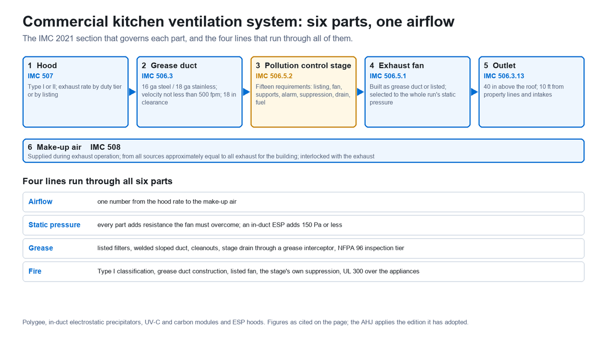
A commercial kitchen ventilation system is the chain of equipment that captures cooking effluent at the hood, carries it through a grease duct, treats it where a pollution control stage is fitted, moves it with a fan, discharges it at an outlet and replaces it with make-up air. Six parts, one design airflow, one chapter of the International Mechanical Code. This page sets out which section governs each part and what to settle first.
The chain can be bought one link at a time. The hood comes with the cookline, the fan with the roofing contractor, the make-up air with the HVAC package, and the pollution control stage last, when a neighbor or a landlord asks for it. Each link is then sized to the number its own supplier was given, and the system fails at whichever link was sized to a different number from the rest.
This page helps you decide what a commercial kitchen ventilation system has to contain, which document decides each part, and in what order the parts are fixed so that one design airflow and one static pressure budget run through all of them. It is the entry point to fourteen detailed guides on this site, each of which takes one part further; this page gives each part its governing section, its one decisive input and its link, and then shows the four lines that run through all six. It does not size a hood, select a fan or make a compliance determination, which belong to your engineer and the authority having jurisdiction.
| Question | Short answer |
|---|---|
| What are the six parts? | Hood, grease duct, pollution control stage, exhaust fan, outlet, make-up air. In the IMC: Sections 507, 506.3, 506.5.2, 506.5.1, 506.3.13 and 508, with Section 509 for fire suppression |
| What is decided first? | The appliance list and fuel. They decide whether a Type I hood is required and which duty tier sets the exhaust rate; the other five parts are sized from that rate |
| What ties the parts together? | Four lines: airflow (one number from hood to make-up air), static pressure (every part adds resistance the fan must overcome), grease (every part must shed or collect it and be cleaned) and fire (every part is either built as a grease duct, listed for the duty or protected) |
| Where does the pollution control stage fit? | In the duct, behind the hood filters and ahead of the fan, with fifteen requirements of its own in IMC Section 506.5.2, from a UL 8782 listing to a factory-installed fire suppression system, a drain through a grease interceptor and a bar on extra-heavy-duty exhaust unless the unit is listed for solid fuel |
| What does a 4,000 cfm heavy-duty line look like? | A 10 ft wall canopy at 400 cfm per foot, a duct no larger than 8 square feet of cross-section, a fan selected at that airflow plus the resistance of the duct, the stage and the outlet, about 4,000 cfm of make-up air at the building, an outlet 40 in above the roof and 10 ft from property lines and intakes, and a quarterly inspection tier if the line charbroils |
| What about the UK? | A specification instead of a code: DW/172, bound through the contract, Approved Document F, insurers and councils; odor and outlet position decided by the council |
| Quick specs on this page | Figure | Basis |
|---|---|---|
| Hood exhaust rate, unlisted wall-mounted canopy | 200, 300, 400 and 550 cfm per linear foot for light, medium, heavy and extra-heavy duty; a listed hood uses its listing | IMC 2021 Section 507.5 |
| Grease duct velocity | Not less than 500 fpm (2.5 m/s) within the duct system; transitions up to 3 ft excepted | IMC 2021 Section 506.3.4 |
| Grease duct material | Steel at least 0.0575 in (16 gage) or stainless steel at least 0.0450 in (18 gage) | IMC 2021 Section 506.3.1.1 |
| Clearance to combustible construction | Not less than 18 in (457 mm) for unenclosed grease duct and exhaust equipment serving a Type I hood | IMC 2021 Sections 506.3.6 and 507 |
| Outlet above the roof | Discharge opening not less than 40 in (1,016 mm) above the roof surface | IMC 2021 Section 506.3.13.1 |
| Make-up air | Supplied during exhaust operation; from all sources approximately equal to all exhaust for the building; mechanical make-up air interlocked with the exhaust | IMC 2021 Section 508.1 |
| Pollution control unit | Fifteen installation requirements, including UL 8782 listing, UL 762 fan, pressure differential alarm, factory-installed fire suppression, 18 in above a roof, drains through a grease interceptor, no extra-heavy-duty exhaust unless listed for solid fuel | IMC 2021 Section 506.5.2 |
| Polygee in-duct precipitator, resistance | Complete in-duct unit with airflow distribution plate at 150 Pa or less, about 0.6 in. w.g. | Polygee model data |
| Polygee ranges | In-duct ESP from 2,000 m³/h; UV-C and carbon modules 3,000 to 15,000 m³/h; HME hood with built-in ESP, 12 sizes, 3,000 to 4,800 m³/h (1,766 to 2,825 cfm) | Polygee model tables |
- Six parts, one airflow: the map of a commercial kitchen ventilation system
- Part 1: the hood decides the type and the rate
- Part 2: the grease duct carries the fire rules
- Part 3: the pollution control stage brings fifteen rules of its own
- Part 4: the fan is sized to a pressure the code never states
- Part 5: the outlet keeps its distances
- Part 6: make-up air balances the building, not the hood
- The four lines that run through all six parts
- A worked example: a 10 ft heavy-duty line at 4,000 cfm
- The UK reading: DW/172 instead of a code
- The Six-Part Ventilation Input Sheet
- Where this guide stops
- Buyer record and key takeaways
- Frequently asked questions
Six parts, one airflow: the map of a commercial kitchen ventilation system
The system has six parts, the air passes through five of them in a fixed order and the sixth replaces what left, and one design airflow, fixed at the hood, is the figure every one of them is sized from. That is the whole map; the rest of this page is the map read one part at a time.
In the order the air travels: the hood captures and confines the cooking effluent at the appliance; the grease duct carries it, liquid-tight and built to contain a fire; the pollution control stage, where one is fitted, treats it, with the electrostatic precipitator removing grease aerosol and smoke and any UV-C or carbon stage acting on the gas-phase odor behind it; the exhaust fan moves the whole column; the outlet discharges it at a position and height the code fixes; and the make-up air system brings an approximately equal amount of air back into the building so that the hood can capture at all. In the United States every one of the six has a section in Chapter 5 of the 2021 International Mechanical Code (IMC), and the fire provisions sit behind them in NFPA 96, the Standard for Ventilation Control and Fire Protection of Commercial Cooking Operations, which the code references rather than reproduces.
| Part | What it does | Governing section, IMC 2021 | The one input that decides it | Our detailed guide |
|---|---|---|---|---|
| 1 Hood | Captures and confines cooking vapors and residues; sets the exhaust rate | 507 (507.1 type, 507.5 capacity, 507 clearances) | The appliance list and fuel, which fix the hood type and the duty tier | Hood code requirements, hood CFM, Type 1 vs Type 2, clearances |
| 2 Grease duct | Carries grease-laden air; contains a fire; sheds grease to cleanouts | 506.3 (materials, joints, slope, cleanouts, velocity, clearance, enclosure) | The design airflow, divided by the 500 fpm velocity floor | Grease duct requirements, duct size |
| 3 Pollution control stage | Removes grease aerosol, smoke and, with odor stages, gas-phase odor before the outlet | 506.5.2 (fifteen installation requirements) | The design airflow and the static pressure the fan can spare | Kitchen exhaust filtration, ecology unit installation |
| 4 Exhaust fan | Moves the design airflow against the resistance of everything else | 506.5.1 (housing built as grease duct or listed for restaurant exhaust duty) | The total static pressure of the run at the design airflow | Exhaust fan requirements |
| 5 Outlet | Discharges the treated or untreated exhaust away from people, openings and intakes | 506.3.13 (above the roof, through a wall, location) | The distances available to property lines, intakes, grade and openings | Termination requirements |
| 6 Make-up air | Replaces the exhausted air so the hood captures and the building stays in balance | 508 (quantity, temperature, balance schedule, compensating hoods) | The sum of all exhaust for the building, not just the hood | Make-up air requirements |
| Across all six | Fire suppression, cleaning, demand control | 509; NFPA 96 inspection tiers; IECC C403.7.5 above 5,000 cfm | Whether the hood is Type I; what the kitchen cooks; the total hood exhaust | Fire suppression, cleaning, demand control |
The table is the order of this page. It is not always the order the parts are bought, which is the problem the page exists to fix.
Part 1: the hood decides the type and the rate
The hood is the head of the chain because two decisions made at the hood propagate through every other part: whether the hood is Type I, which switches on the grease duct, fire suppression and cleaning provisions, and the exhaust rate, which every other part is sized to.
Type I or Type II: what the appliance sends into the air
Section 507.1 of the IMC requires commercial kitchen exhaust hoods to be Type I or Type II, designed to capture and confine cooking vapors and residues, and installed at or above appliances; where any cooking appliance under a single hood requires a Type I hood, the whole hood is Type I. The split is by what leaves the appliance: grease and smoke call for a Type I hood, heat, steam and moisture alone for a Type II, and our Type 1 versus Type 2 guide walks the appliance list that decides it. A Type II hood’s duct is ordinary rigid metal under Section 506.4; a Type I hood’s duct is a grease duct under Section 506.3, and that one classification is what brings the material, welding, slope, clearance, suppression and cleaning rules of the rest of this page into play.
The exhaust rate: a table, or a listing
Section 507.5 requires commercial food service hoods to exhaust a minimum net quantity of air determined by duty tier, with the net quantity calculated by subtracting any air supplied directly into the hood cavity from the total exhaust. For an unlisted wall-mounted canopy the tiers in Sections 507.5.1 to 507.5.4 run from 200 cfm per linear foot over light-duty appliances through 300 for medium duty and 400 for heavy duty to 550 for extra-heavy duty, with single island canopies higher and backshelf and eyebrow hoods not permitted at the heaviest tier; a hood listed to UL 710 may exhaust the rate on its listing instead, which can be lower. Our hood CFM requirements guide gives the full table by hood style and explains why the listed number can legitimately be smaller. The point for this page is simpler: the rate fixed here is the one number that the duct, the fan, the make-up air and the pollution control stage all have to be designed around, and a project that lets a later supplier size to a different number has broken the chain before anything is installed.
Three further decisions live at the hood and are covered on their own pages: the clearances, starting with 18 in (457 mm) from a Type I hood to combustible construction and continuing through overhang, lip height and filter distance, in our clearance requirements guide; the listed grease filters, which plan review checks and mesh filters alone do not satisfy; and the eleven-point checklist a reviewer walks from the cookline to the outlet, in hood code requirements. Where the canopy and the first filtration stage are bought together, our HME hood with built-in ESP is a Type I canopy in 12 sizes rated 3,000 to 4,800 m³/h, which puts the particle stage inside the hood and leaves the duct, fan and outlet rules unchanged.
Part 2: the grease duct carries the fire rules
Everything downstream of a Type I hood is part of the Type I exhaust system, and the grease duct is where the fire code is most specific, because the duct is where a fire has fuel. The rules are short, and they all follow from one fact: the air carries grease.
Material, joints, slope and cleanouts
Section 506.3.1.1 requires grease ducts serving Type I hoods to be steel at least 0.0575 in thick, 16 gage, or stainless steel at least 0.0450 in, 18 gage. The joints are made with a continuous liquid-tight weld or braze, the duct slopes toward the hood or a grease reservoir, cleanouts are placed wherever the run cannot otherwise be reached, and where the duct passes through the building it is enclosed in a rated shaft or wrapped in a listed enclosure. Our grease duct requirements guide takes those in the order a drawing is reviewed, with the slope figure, the cleanout spacing and the difference between the IMC and NFPA 96 on each. One rule from Section 506.3.6 recurs at every part of this page: unenclosed grease duct and exhaust equipment serving a Type I hood keep not less than 18 in (457 mm) from combustible construction.
Why the duct is not sized larger to be safe
Section 506.3.4 sets a floor on velocity, not a diameter: grease duct systems serving a Type I hood are designed and installed to provide an air velocity within the duct system of not less than 500 feet per minute, 2.5 m/s, with an exception only for transitions up to 3 ft long that connect the duct to differently sized hood and fan openings and are designed not to trap grease. The velocity floor is what makes the duct different from a domestic kitchen’s: a larger duct lowers the velocity, lets grease settle and defeats the cleanout spacing. So the duct cross-section has a ceiling, the design airflow divided by 500 fpm, and our exhaust duct size guide works the arithmetic and the consequences for the fan. The same floor is the first thing to check when a pollution control stage is added to an existing duct: the airflow that actually exists in that duct, not the hood’s nameplate, is the number the stage is selected against.
Part 3: the pollution control stage brings fifteen rules of its own
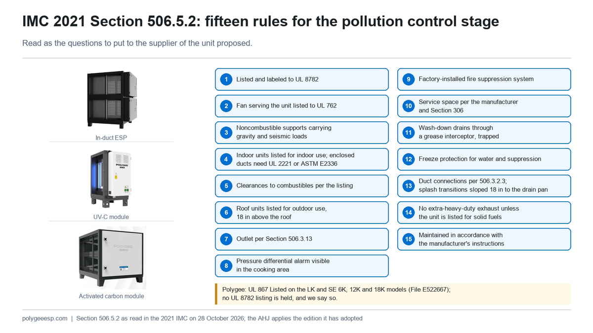
The pollution control stage is the part that can be added last and designed in least, and in the 2021 IMC it carries a list of its own: Section 506.5.2 gives fifteen requirements, and every one of them is a question to put to the supplier of the unit proposed. We make this equipment, so this section is written with that disclosure in front of it: the list below is the code’s, not ours, and the right-hand column states what is confirmed per model and what we do not hold.
What the stage does, and in what order
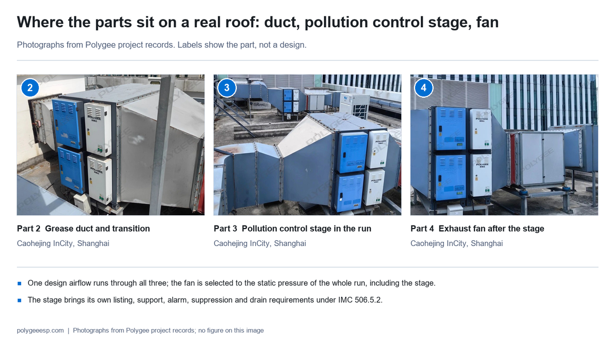
The stage treats what leaves the hood filters. Grease aerosol and smoke particles fine enough to pass the hood filters are collected in an electrostatic precipitator; gas-phase odor, which passes any particle stage, is addressed by a UV-C stage, an activated carbon bed or both, in that order and only after the particle stage, because grease blinds carbon and fouls lamps. Our kitchen exhaust filtration guide sets out the stages, what each removes and does not, and the airflow and menu bands that decide the list; what matters here is that the stage sits in the grease duct between the hood and the fan, that it adds resistance the fan must overcome, and that it is itself equipment serving a Type I hood, with everything that classification carries.
IMC Section 506.5.2: the fifteen requirements, read as supplier questions
| Section 506.5.2 item | What the code requires | The question to put to the supplier | Where Polygee stands |
|---|---|---|---|
| 1 Listing | Pollution-control units shall be listed and labeled in accordance with UL 8782 | Is the model proposed listed to UL 8782, under which file, and does the listing cover this airflow? | Our LK and SE 6K, 12K and 18K models are UL 867 Listed under File E522667; we hold no listing to UL 8782, and we say so. Where the authority applies this item, a UL 8782 listed unit is required |
| 2 Fan | Fans serving pollution-control units shall be listed and labeled in accordance with UL 762 | Is the fan on the drawing listed for restaurant exhaust duty? | We do not make fans; the fan is selected by your engineer, see Part 4 |
| 3 Supports | Bracing and supports noncombustible, attached to the structure, carrying gravity and seismic loads within IBC limits | What does the unit weigh, as separate point loads per module? | Published per model; in our 8,000 m³/h three-stage example the modules total 386 kg, the carbon stage 215 kg of it |
| 4 Indoor location | Indoor units listed for indoor use; where connected to enclosed ducts, listed to UL 2221 or ASTM E2336 for location in an enclosure of the same fire-resistance rating | Is the unit listed for indoor installation and, if the duct is enclosed, for that enclosure rating? | A listing question answered per model; see item 1 |
| 5 Clearance | Clearances to combustible material maintained in accordance with the listing | What clearance does the listing state? | Confirmed per model with the listing; the 18 in of Section 506.3.6 applies to unenclosed grease duct and exhaust equipment serving a Type I hood |
| 6 Roof mounting | Roof-mounted units listed for outdoor installation and mounted not less than 18 in (457 mm) above the roof | Is the model listed for outdoor use, and what is the curb height? | Whether a model is listed for outdoor use is confirmed in writing per model; the curb is the installer’s |
| 7 Outlet | Exhaust outlets for pollution-control units in accordance with Section 506.3.13 | Where does the outlet end, and does it make the Part 5 distances? | The unit does not shorten any distance; see Part 5 |
| 8 Pressure alarm | An airflow differential pressure control monitoring the drop across the filter sections, with a visual alarm in the cooking area when airflow falls below the design velocity | Is a differential pressure switch and alarm supplied, and where is it displayed? | To be specified by the engineer; we state in writing whether the model carries a differential pressure switch and where its signal can go |
| 9 Fire suppression | Pollution-control units provided with a factory-installed fire suppression system | Does the unit ship with its own suppression, and how is it tied into the hood system? | Whether a model ships with factory-installed suppression is confirmed in writing per model; the hood system protects the appliances, plenum and duct, and the unit’s protection is a separate item on the suppression drawing, see our fire suppression guide |
| 10 Service space | Service space per the manufacturer’s instructions and Section 306 | What clear space does each module need on its access side? | Our UV and carbon modules publish D = 1,000 mm on the access side; the precipitator needs the clear length to withdraw its cell, confirmed per model |
| 11 Drains | Wash-down drains discharging through a grease interceptor, sized for the flow, sealed with a trap or other approved means; a trap’s seal depth accounts for system pressurization and evaporation | Where does the wash water go, and who supplies the interceptor and trap? | The drain connection and its position are confirmed per model; the interceptor and the trap or other approved seal are the plumbing contractor’s |
| 12 Freeze protection | Water supply and fire suppression protected from freezing where subject to it | Is the unit outdoors in a freezing climate, and what is heat-traced? | A site question; the washing arrangement and any water supply for the model are confirmed with the quotation |
| 13 Duct connections | Connections per Section 506.3.2.3; where wash water can splash or carry over into the transition, it slopes toward the cabinet drain pan for a length of at least 18 in; ducts transition to the full size of the unit’s inlet and outlet | How are the transitions built and sloped at the unit? | Transitions to the full inlet and outlet size, with the slope where wash water can splash or carry over, are shown on the installation drawing for the model |
| 14 Extra-heavy duty | Extra-heavy-duty appliance exhaust systems shall not be connected to pollution-control units except where the unit is specifically designed and listed for use with solid fuels | Is any solid-fuel appliance on the line, and is the unit listed for solid fuel? | Our in-duct units are not offered for solid-fuel exhaust unless that listing is confirmed in writing for the model; a solid-fuel line is a separate exhaust system |
| 15 Maintenance | Pollution-control units shall be maintained in accordance with the manufacturer’s instructions | What does the manual require, and how often? | The washing and inspection routine is in the manual supplied with the model; the interval depends on the cooking load, so no figure is given here |
The table restates Section 506.5.2 of the 2021 IMC as we read it on 28 October 2026 and our own listings as recorded in our certificate file; it does not say which items a given authority applies, which depends on the edition adopted, and it does not claim a listing we do not hold. The practical reading is this: the stage is not a filter box dropped into a duct. It is exhaust equipment with its own listing, support, clearance, suppression, drainage, fuel and service questions, and the time to ask them is before the duct route is fixed, because items 3, 10, 13 and 14 decide where the unit can physically go and whether it may be connected at all, which is the subject of our ecology unit installation guide.
Part 4: the fan is sized to a pressure the code never states
The fan is where the other five parts present their bill. The code tells you what the fan must be; it does not tell you what the fan must overcome, and the second number is the one that decides whether the hood captures on opening day.
What the fan must be
Under Section 506.5.1 an exhaust fan serving a Type I hood has its housing constructed as a grease duct under Section 506.3.1.1 or is listed and labeled for restaurant exhaust duty; the listing standard was UL 762, merged in June 2021 into UL 705 as Supplement SC with the requirements unchanged. Section 506.5.1.1 keeps the fan motor outside the exhaust airstream, and where an enclosed duct system is connected to an in-line fan that is not outdoors, Section 506.5.1.2 puts the fan in a room or space with the same fire-resistance rating as the duct enclosure, with access for servicing and cleaning and ventilation per the fan manufacturer’s instructions. The three fan types, upblast, utility set and in-line, their drainage and access, and the interlock with the cooking appliances are in our exhaust fan requirements guide; we do not make fans, and that page is written as a reader of the code rather than a seller of the equipment.
What the fan must overcome
The fan is selected to deliver the design airflow of Part 1 against the total static pressure of the run: the hood and its filters, the duct with its length, fittings and velocity, the pollution control stage where one is fitted, and the outlet. The code sets none of those resistances; the equipment data and the duct design do. For our equipment the figure is published: a complete in-duct precipitator with its airflow distribution plate is rated at 150 Pa or less, about 0.6 in. w.g., and the UV-C and carbon modules carry their own resistance by model, so a three-stage train is three additions, not one. A fan selected to the hood and duct alone, with the stage added afterwards, can deliver less than the design rate at the new static pressure, and the symptom arrives as a hood that no longer captures; a buyer in Dubai can meet exactly that question when a precipitator and carbon module are added to an existing system and the capture gets worse: the fan curve, the static pressure and the make-up air are checked before the equipment is blamed. The stage count is therefore reviewed against the pressure the fan has to spare before the layout is drawn, not after.
Part 5: the outlet keeps its distances
The outlet is governed by distances that no in-duct equipment shortens, and by a nuisance clause that in-duct equipment is one answer to. Both halves matter, and they are decided by different people.
Section 506.3.13 governs exhaust outlets serving Type I hoods. Above the roof, Section 506.3.13.1 puts the discharge opening not less than 40 in (1,016 mm) above the roof surface. Through an exterior wall, Section 506.3.13.2 permits a termination only where the smoke, grease, gases, vapors and odors in the discharge do not create a public nuisance or a fire hazard, not where the building code requires protected openings, not within 3 ft (914 mm) of any opening in the exterior wall, and in accordance with Section 506.3.13.3 on location, which keeps the outlet not less than 10 ft (3,048 mm) horizontally from parts of the same or contiguous buildings, adjacent buildings and adjacent property lines, not less than 10 ft above adjoining grade, and not less than 10 ft horizontally from or 3 ft (914 mm) above air intake openings into any building, with an exception allowing 5 ft (1,524 mm) horizontally where the outlet discharges away from those locations, as our termination requirements guide sets out with the rooftop and wall cases side by side. Those distances decide where the outlet goes; what comes out of it, and whether a wall outlet survives the nuisance clause, is decided by the treatment in Part 3 and by the reviewer. Outside the United States the question of whether a treated discharge may sit low or near windows is answered differently by councils, certifiers and building departments, and our low-level discharge guide sets out the UK, Australian and Canadian answers.
Part 6: make-up air balances the building, not the hood
Make-up air is easy to undersize, because the rule that governs it is written at the building and read at the hood. Section 508.1 is short and contains no flow rate: make-up air shall be supplied during the operation of commercial kitchen exhaust systems; the amount supplied to the building from all sources shall be approximately equal to the amount of exhaust air for all exhaust systems for the building; the make-up air shall not reduce the effectiveness of the exhaust system; it may be provided by gravity or mechanical means or both; and mechanical make-up air systems shall be automatically controlled to start and operate simultaneously with the exhaust.
Two of those sentences do most of the work. The balance is drawn at the building, so a kitchen matched hood-for-hood can still fall short because restrooms, a dishwasher and a laundry all exhaust on the same account; and the air can arrive by several routes, one of them capped by the energy code and one of them not counting toward what the hood owes, which our make-up air requirements guide follows route by route, with the 10 °F (6 °C) temperature limit of Section 508.1.1, the outdoor air balance schedule of Section 508.1.2 and the compensating hood label of Section 508.2. Where the total hood exhaust exceeds 5,000 cfm the energy code adds a threshold of its own, with demand control ventilation one of three ways through it, and our demand control kitchen ventilation guide explains why crossing it also forces listed hoods and caps each hood’s rate, and what a system that turns down does to equipment that was selected at full airflow.
The four lines that run through all six parts
The six parts are described separately above, and the failures happen between them. Four lines run through all six, and a design that follows each line from the hood to the make-up air catches the mismatches this page describes before equipment is ordered.
| Line | Starts at | Passes through | Ends at | What breaks when a part is sized to a different number |
|---|---|---|---|---|
| Airflow | The hood rate, Section 507.5, or the listing | Duct cross-section (rate divided by 500 fpm), stage selection at that airflow, fan duty point | Make-up air approximately equal to all exhaust, Section 508.1 | A duct sized larger lets grease settle; a stage selected at nameplate rather than actual airflow passes particles; make-up air short of exhaust starves the hood |
| Static pressure | The hood and filters | Duct length and fittings, the stage’s resistance (150 Pa or less for our in-duct unit, more per added module), the outlet | The fan, selected to deliver the airflow at that total | A fan selected before the stage was added moves less than the design rate; a demand control system that turns down moves away from the airflow everything was selected at |
| Grease | Listed hood filters | Welded, sloped duct with cleanouts; the stage’s collector cells and wash-down drain through a grease interceptor | The outlet, and the inspection tier of NFPA 96 | Mesh filters that are not listed; cleanouts missing on an inaccessible run; a stage with no drain; an inspection interval read as a cleaning calendar |
| Fire | The Type I classification | Grease duct material and 18 in clearance or enclosure; fan built as a grease duct or listed; the stage’s own factory-installed suppression, Section 506.5.2 item 9 | The suppression system over the appliances, plenum and duct, UL 300 for pre-engineered systems, with a pull station and fuel and power shutoff | A unit added to the run without its own protection; a fan room without the enclosure’s rating; equipment inside the 18 in |
Grease and fire have a maintenance line of their own that runs after commissioning. NFPA 96 sorts cooking operations into four inspection tiers, solid fuel monthly, high-volume quarterly, moderate-volume semiannually and low-volume or seasonal annually, and those are inspection intervals rather than a cleaning calendar: cleaning happens when the inspection finds grease past the allowed limit, as our exhaust cleaning requirements guide explains, with who is allowed to do the work and how washable cells and replaceable media change the recurring bill.
A worked example: a 10 ft heavy-duty line at 4,000 cfm
The example is dimensional arithmetic through the six parts, not a design: it uses the IMC table rates and our published equipment figures, and every number on a real project is replaced by the engineer’s. Take a 10 ft wall-mounted canopy over a heavy-duty line, a gas charbroiler and a wok range with no solid fuel, in a US jurisdiction on the 2021 IMC; a solid-fuel appliance would be extra-heavy duty, on its own exhaust system, and outside this example.
| Part | The figure in the example | Where it comes from | What it commits the next part to |
|---|---|---|---|
| 1 Hood | Type I, because the charbroiler and wok produce grease and smoke. Unlisted wall canopy, heavy duty: 400 cfm per linear foot × 10 ft = 4,000 cfm, about 6,800 m³/h. A UL 710 listed hood would use its listed rate instead | IMC 507.1, 507.5.2 | 4,000 cfm is the number for Parts 2 to 6 |
| 2 Grease duct | Maximum cross-section 4,000 cfm ÷ 500 fpm = 8.0 ft²; the duct is sized below that so velocity stays above the floor. 16 gage steel or 18 gage stainless, liquid-tight welds, sloped, cleanouts where the run cannot be reached, 18 in to combustibles or an enclosure through the building | IMC 506.3.4, 506.3.1.1, 506.3.6 | The route length and fittings go into the static pressure; the enclosure rating goes into Part 3 item 4 and Part 4 |
| 3 Pollution control stage | An in-duct electrostatic precipitator whose rated airflow band contains 6,800 m³/h, confirmed per model, behind the hood filters and a spark arrester for the charbroiler. Resistance 150 Pa or less, about 0.6 in. w.g., for the complete unit with its distribution plate. If an odor condition exists, UV-C and carbon modules follow, each with its own resistance and D = 1,000 mm access; three modules in our 8,000 m³/h example total 4,462 mm of envelope length and 386 kg as three point loads | Polygee model data; IMC 506.5.2 items 3, 10, 13 | Item 1 listing is confirmed with the authority; item 8 alarm and item 9 suppression go on the drawings; item 11 drain goes to the plumber |
| 4 Exhaust fan | Listed for restaurant exhaust duty, selected to deliver 4,000 cfm at the total of hood, duct, stage and outlet resistance; the precipitator adds up to 0.6 in. w.g. to the same run without it, and each odor module adds its own published figure | IMC 506.5.1; fan manufacturer’s curve | The duty point is written on the schedule with the stage included |
| 5 Outlet | Rooftop, discharge opening at least 40 in above the roof, 10 ft from property lines, adjacent buildings and other parts of the building, 10 ft above grade, 10 ft from or 3 ft above any air intake | IMC 506.3.13 | The intake positions in Part 6 are checked against the same distances |
| 6 Make-up air | Make-up air for the building approximately equal to all its exhaust: this hood’s 4,000 cfm plus the restrooms, dishwasher and any other exhaust, from all sources, within 10 °F of the space, interlocked with the exhaust, on an outdoor air balance schedule | IMC 508.1, 508.1.1, 508.1.2 | Below 5,000 cfm total hood exhaust the energy code threshold is not crossed |
| Across all six | UL 300 suppression over the appliances, plenum and duct with a pull station; the stage’s own factory-installed suppression; charbroiling puts the operation in the high-volume tier, inspected quarterly | IMC 509; NFPA 96 inspection tiers | The cleaning contract is written as inspection intervals, with cleaning when grease is found |
Read the example for its shape rather than its figures. The 4,000 cfm was fixed once, at the hood, and reappears in every row; the stage appeared in the static pressure row before the fan was selected, not after; the outlet and the intake were checked against each other; and the suppression drawing has two items, not one. A project that produces this table before any purchase order has given its engineer one consistent chain to design from; a project that produces it afterwards is finding out which part was sized to a different number.
The UK reading: DW/172 instead of a code
The United Kingdom arrives at the same six parts through a specification rather than a code, and through a council rather than an authority having jurisdiction. DW/172, the Building Engineering Services Association’s Specification for Kitchen Ventilation Systems, is the document a UK consultant means when a tender says the extract system shall comply; the current text is the second edition of 2018 with addenda from April 2020 and May 2024. It is not a statute. It binds a project through the contract that cites it, through Approved Document F in England, which points commercial kitchens to it, and through the insurers and councils that write its provisions into conditions. It allows one extract-rate method, sets the canopy overhang and the separator height in millimeters, tests the grease separators, spaces the access doors, fixes the discharge velocity and gives the electrostatic precipitator one job with two conditions attached, all of which our DW/172 guide sets out clause by clause.
Two differences from the US chain matter to a buyer working in both. The odor stages and the outlet position are not fixed by the specification; they are decided by the council under the planning and statutory nuisance framework, using a scoring method and a hierarchy of discharge options, which our UK odour control page explains. And the demand control provision arrives at almost the same threshold as the American energy code by a different route, recommended rather than required, while the make-up air section carries requirements of its own, which the make-up air and demand control guides above put alongside their US sections. Projects in Australia, Canada, Singapore and the Gulf each have a page of their own on this site, because each decides the outlet and the treatment under its own documents.
The Six-Part Ventilation Input Sheet
The sheet is the record to fill before the first purchase order, one row per part, so that every supplier receives the same airflow and every reviewer sees the same chain. It is written to be handed to the consultant and to us in the same form.
The Six-Part Ventilation Input Sheet: for each part, who decides it, the input to supply, who supplies the number, and which of the four lines it sits on.
| Part | Decided by | Input to record | Who supplies it | Lines it sits on |
|---|---|---|---|---|
| 1 Hood | IMC 507 and the hood listing; the AHJ | Appliance list with fuel and duty tier; hood style and length; listed or unlisted; design exhaust rate in cfm and m³/h; clearances available | Owner and kitchen designer; hood manufacturer | Airflow, grease, fire |
| 2 Grease duct | IMC 506.3; NFPA 96 | Route and length; fittings; cross-section against the 500 fpm floor; enclosure or 18 in clearance; cleanout positions | Mechanical engineer; duct contractor | Airflow, static pressure, grease, fire |
| 3 Pollution control stage | IMC 506.5.2; the AHJ on which items apply | Stages required and why (particle, odor, both); position and access side; resistance per module at the design airflow; weight per module; listing held; suppression and drain arrangement | The unit supplier, in writing per model | Airflow, static pressure, grease, fire |
| 4 Exhaust fan | IMC 506.5.1; UL 705 SC listing | Fan type; duty point at design airflow and total static pressure including the stage; interlock | Mechanical engineer; fan manufacturer | Airflow, static pressure, fire |
| 5 Outlet | IMC 506.3.13; the AHJ on the nuisance clause | Rooftop or wall; distances to property lines, buildings, grade, intakes and openings; who else is within reach of the plume | Mechanical engineer; the AHJ | Airflow, grease |
| 6 Make-up air | IMC 508; the energy code above 5,000 cfm | All exhausts for the building; routes and quantities; temperature limit; balance schedule; intake positions against Part 5 | Mechanical engineer | Airflow |
| Across all six | IMC 509; NFPA 96; the fire authority | Suppression coverage list including the stage; inspection tier; cleaning contract written as inspection intervals | Fire protection contractor; operator | Grease, fire |
Two things the sheet does not do. It does not tell you what an authority will accept, which is decided on the documents submitted and the edition adopted; and it does not replace the fourteen detailed guides, each of which carries the clause text, the exceptions and the figures this page has summarized.
Where this guide stops
Four things are deliberately left to other documents. The clause text of NFPA 96, ASHRAE 154, UL 710, UL 8782 and DW/172, because each is a paid document and this page names them where they apply rather than reproducing them. The exhaust rates for hood styles other than the wall-mounted canopy, the duct slope and cleanout figures, the make-up air routes and the suppression coverage list, because each has its own page here with the clause and its exceptions. Any statement that a unit of ours satisfies Section 506.5.2 item 1, because we hold UL 867 on the listed models and no UL 8782 listing. And any compliance determination, because the authority having jurisdiction applies the edition it has adopted and the amendments its jurisdiction has made.
Three layers of acceptance apply here as to every part on the page. Equipment data describe the parts: a hood’s listing, a duct’s gage, a stage’s resistance and weight, a fan’s curve. The installation decides whether the parts were put together to one airflow and one pressure, with the clearances, access and drains the code asks for. The system in operation is what the inspector, the fire authority and the neighbor judge. A part can pass the first layer and the system still fail the third, which is why the input sheet is filled before the orders rather than after the complaints.
Buyer record and key takeaways
Before any part of the system is ordered, these items are in your file.
- The appliance list with fuel and duty tier, and the hood type and rate that follow from it, with the code edition or the listing the rate was taken from.
- The design airflow written once, in cfm and m³/h, and the same figure on every supplier’s quotation.
- The duct route with its cross-section checked against the 500 fpm floor and its enclosure or clearance decided.
- For a pollution control stage, the fifteen questions of Section 506.5.2 answered in writing per model, with the resistance and weight per module.
- The fan duty point at the design airflow and the total static pressure including the stage.
- The outlet position with its distances, and the make-up air routes with the building balance schedule.
- The suppression coverage list with the stage on it, and the NFPA 96 inspection tier the operation falls in.
Key takeaways
- Six parts, one airflow. Hood, grease duct, pollution control stage, fan, outlet and make-up air are governed by IMC Sections 507, 506.3, 506.5.2, 506.5.1, 506.3.13 and 508, and the rate fixed at the hood is the number every other part is sized to.
- The hood decides first. The appliance list fixes whether the hood is Type I and which duty tier sets the exhaust rate, 200 to 550 cfm per linear foot on an unlisted wall canopy or the listing’s figure.
- The duct has a ceiling, not a floor. The 500 fpm velocity floor caps the cross-section at the airflow divided by 500, and a larger duct is a grease trap, not a margin.
- The stage brings fifteen rules. Section 506.5.2 asks for a UL 8782 listing, a UL 762 fan, supports, clearances, a pressure alarm, factory-installed suppression, service space, a drain through a grease interceptor, no extra-heavy-duty exhaust unless listed for solid fuel, and maintenance per the manual; we hold UL 867 on our listed models and no UL 8782, and say so.
- The fan pays for everything. It is selected to the design airflow at the total static pressure of the run, including the stage’s 150 Pa or less for our in-duct unit, and a fan selected before the stage was added can deliver less than the design rate.
- The Six-Part Ventilation Input Sheet is the record to fill before the first purchase order, so that every supplier and reviewer works from the same chain.
Frequently asked questions
- What are the parts of a commercial kitchen ventilation system?
- Six, in the order the air travels: the hood that captures the cooking effluent, the grease duct that carries it, the pollution control stage that treats it where one is fitted, the exhaust fan that moves it, the outlet that discharges it, and the make-up air that replaces it. In the United States the International Mechanical Code governs each of them in Chapter 5: hoods in Section 507, grease ducts and outlets in Section 506.3, fans and pollution control units in Section 506.5, make-up air in Section 508 and fire suppression in Section 509, with NFPA 96 behind the fire provisions. One design airflow has to run through all six.
- What should be decided first when designing a commercial kitchen ventilation system?
- The appliance list and its fuel, because they decide whether a Type I hood is required and which duty tier sets the exhaust rate; everything else is sized from that rate. Under IMC Section 507.5 an unlisted wall-mounted canopy exhausts 200, 300, 400 or 550 cfm per linear foot for light, medium, heavy and extra-heavy duty, and a hood listed to UL 710 may use the rate on its listing. Once the rate is fixed, the duct cross-section follows from the 500 fpm velocity floor, the fan from the static pressure of the whole run, the make-up air from the building balance, and the pollution control stage from the airflow and the pressure the fan has left.
- Does adding an electrostatic precipitator change the fan or the make-up air?
- It changes the fan selection and leaves the make-up air quantity alone. A complete in-duct precipitator of ours with its airflow distribution plate is rated at 150 Pa or less, about 0.6 inches of water, and that resistance is added to the static pressure the fan must develop at the design airflow; a fan selected without it can move less air than the hood was designed for. The make-up air stays approximately equal to the exhaust under IMC Section 508.1, because the stage changes what leaves the duct, not how much. Under Section 506.5.2 the unit also brings its own requirements: a listing, a fan listed for the duty, a pressure differential alarm, a factory-installed fire suppression system, service space and a drain through a grease interceptor.
- How does the UK differ from the US on commercial kitchen ventilation?
- The UK works from a specification rather than a code: DW/172, the Building Engineering Services Association’s Specification for Kitchen Ventilation Systems, second edition 2018 with addenda in April 2020 and May 2024. It is not a statute; it binds a project through the contract that cites it, through Approved Document F in England, which points commercial kitchens to it, and through the insurers and councils that write its provisions into conditions. It allows one extract-rate method, sets the canopy overhang and separator height in millimeters, tests the grease separators, spaces the access doors, fixes the discharge velocity, and gives the electrostatic precipitator one job with two conditions attached. Odor and discharge position are then decided by the council under the planning and nuisance framework.
Designing the chain, or adding a stage to one that exists?
Send us the Six-Part Ventilation Input Sheet as far as you have filled it: the appliance list and duty tier, the design airflow, the duct route and the actual airflow in it if the duct exists, the static pressure the fan has to spare, the position and access side available for the stage, the outlet and intake positions, and the wording of any odor condition. You get back the stage list for that airflow, the resistance and weight per module, the access each module needs, the installation drawing for the model, the listings each model carries and does not, and a note of which items of Section 506.5.2 fall to your engineer, your fire contractor and your plumber rather than to us. The hood rate, the fan selection and the authority’s acceptance stay with your engineer and the authority.
If the stage is already chosen, the in-duct electrostatic precipitator page covers the particle stage and its test reports, and the kitchen ecology unit page covers the three-stage train and its airflow bands.
Why we write this. The fourteen guides on this site each take one part of the chain to its clause and its exceptions; this page is the chain itself: six parts in the order the air travels, the section that governs each, the one input that decides it, the four lines that run through all of them, and one worked example that shows the same airflow appearing in every row. It gives no clause text from a paid document, claims no listing we do not hold, and makes no compliance determination.
Law manages project delivery at Polygee. Polygee, founded in 2004, manufactures the in-duct electrostatic precipitators, UV-C and activated carbon modules, kitchen ecology units and ESP hoods named here and has exported to 50 countries; it does not make conventional hoods, grease ducts, fans or suppression systems. The code sections cited on this page were read in the 2021 International Mechanical Code as published by the International Code Council; equipment figures are from third-party test reports and Polygee’s published model tables, and no figure is given where the record holds none.
References & further reading
- International Code Council, 2021 International Mechanical Code, Chapter 5 Exhaust Systems: Sections 506.3 (grease ducts, including 506.3.1.1, 506.3.4, 506.3.6, 506.3.13), 506.4, 506.5.1, 506.5.2 (pollution-control units), 507 (commercial kitchen hoods, including 507.1 and 507.5), 508 (makeup air) and 509 (fire suppression systems). codes.iccsafe.org
- National Fire Protection Association, NFPA 96, Standard for Ventilation Control and Fire Protection of Commercial Cooking Operations, product page. nfpa.org
- ASHRAE, ANSI/ASHRAE Standard 154-2016, Ventilation for Commercial Cooking Operations, standard page. ashrae.org
- UL Standards & Engagement, UL 710, Standard for Exhaust Hoods for Commercial Cooking Equipment, standard page. shopulstandards.com
- Building Engineering Services Association, DW/172 Specification for Kitchen Ventilation Systems, second edition 2018 with addenda, publication page. publications.thebesa.com
Related reading
- Commercial kitchen hood code requirements: the eleven-point checklist plan review walks from the cookline to the outlet, and the four points that send projects back.
- Commercial kitchen exhaust fan requirements: the fan as part of the grease duct system, the three fan types, and where the ESP enters the static pressure.
- Kitchen exhaust filtration: which stages a kitchen needs, in what order, and what each removes and does not.
- Ecology unit installation: the straight run, weight, pressure and access a three-stage train needs before anyone orders one.